Table of Contents
Advertisement
Quick Links
Advertisement
Table of Contents

Related Manuals for Crestron QM-FTDC QuickMedia


Summary of Contents for Crestron QM-FTDC QuickMedia
- Page 1 Crestron QM-FTDC QuickMedia™ FlipTop Data Center Operations & Installation Guide...
- Page 2 This document was prepared and written by the Technical Documentation department at: Crestron Electronics, Inc. 15 Volvo Drive Rockleigh, NJ 07647 1-888-CRESTRON All brand names, product names and trademarks are the property of their respective owners. ©2007 Crestron Electronics, Inc.
-
Page 3: Table Of Contents
Appendix B: QuickMedia Installation and Compensation ............38 Installation Notes....................... 38 Compensation......................38 Compatibility Charts ....................40 Return and Warranty Policies ....................42 Merchandise Returns / Repair Service ..............42 CRESTRON Limited Warranty................. 42 Contents • i Operations & Installation Guide – DOC. 6312B... -
Page 5: Quickmedia™ Fliptop Data Center: Qm-Ftdc
QuickMedia™ FlipTop Data Center: QM-FTDC Introduction Features and Functions The QM-FTDC FlipTop Data Center is part of the Crestron MediaManager™ line of network devices, room control systems and signal routing solutions. It is available in six different models. Models DESCRIPTION... - Page 6 Easy setup using Crestron SystemBuilder™ software • Optional cable management kit As an option, custom-engraved buttons can be designed and obtained by using the Crestron Engraver software. Version 2.2.2.3 and Crestron Database 16.3.4 or later are available from the Crestron website (at http://www.crestron.com/).
- Page 7 Crestron SystemBuilder™ software. ® Cresnet Cresnet is the communications backbone for many Crestron touchpanels, keypads, lighting controls and other devices. The Cresnet bus is a simple, yet flexible 4-wire network that provides rock-solid bidirectional communication and power for up to 252 Cresnet devices.
-
Page 8: Internal Block Diagram
FlipTop Data Center Crestron QM-FTDC Internal Block Diagram The following diagram represents the interfacing abilities of the QM-FTDC. This Cresnet device uses QuickMedia technology to facilitate simplified connection of audio, video and computer equipment. All media and control signals are routed via a single QuickMedia cable for easy installation. -
Page 9: Specifications
Crestron QM-FTDC FlipTop Data Center Specifications Specifications for the QM-FTDC are listed in the following table. QM-FTDC Specifications SPECIFICATION DETAILS RGB/Video Signal Types RGB and component video RGB Formats RGBHV, RGBS or RG Video/HDTV Formats NTSC or PAL, HDTV up to 1080i/1080p... - Page 10 1. Component video or HDTV may require a suitable VGA-to-component adaptor or breakout cable (not included). 2. The latest software versions can be obtained from the Crestron website. Refer to the NOTE following these footnotes. 3. Crestron 2-Series control systems include the AV2 and PRO2. Consult the latest Crestron Product Catalog for a complete list of 2-Series control systems.
-
Page 11: Physical Description
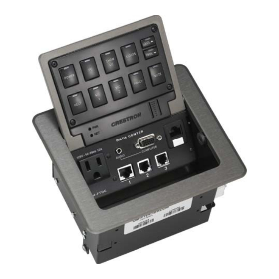
Crestron QM-FTDC FlipTop Data Center Physical Description This section provides information on the connections, controls and indicators available on your QM-FTDC. Refer to the physical views shown below. QM-FTDC Physical View (Top Open) QM-FTDC Overall Dimensions (Top View) QMI-FTDC Overall Dimensions (Top View) 8.50 in... - Page 12 FlipTop Data Center Crestron QM-FTDC QM-FTDC-NB (Top View) NOTE: The physical dimensions of the NB models are identical to the models with keypad. QM-FTDC Overall Dimensions (Front View) QMI-FTDC Overall Dimensions (Front View) 5.22 in 13.24 cm 7.05 in 17.90 cm 6.25 in...
- Page 13 Crestron QM-FTDC FlipTop Data Center QM-FTDC (Bottom View) QMI-FTDC (Bottom View) QM-FTDC Overall Dimensions (Rear View) QMI-FTDC Overall Dimensions (Rear View) 2.99 in 2.32 in (7.60 cm) (5.88 cm) 4.58 in 4.32 in (11.61 cm) (10.96 cm) 5.58 in 5.39 in (14.17 cm)
- Page 14 FlipTop Data Center Crestron QM-FTDC QM-FTDC Overall Dimensions (Side View) QMI-FTDC Overall Dimensions (Side View) 5.51 in 14.00 cm 6.17 in 4.64 in 15.68 cm 11.77 cm 5.21 in 13.23 cm QM-FTDC Connectors, Controls & Indicators QM-FTDC Connectors, Controls & Indicators...
- Page 15 Crestron QM-FTDC FlipTop Data Center Connectors, Controls & Indicators CONNECTORS DESCRIPTION CONTROLS & INDICATORS KEYPAD Programmable keypad allowing variable combinations of large and small engravable buttons, 10 minimum (all large) to 20 maximum (all small); ships with 10 large buttons (small buttons and engraving sold...
- Page 16 FlipTop Data Center Crestron QM-FTDC Connectors, Controls & Indicators (Continued) CONNECTORS DESCRIPTION CONTROLS & INDICATORS (1) 8-pin RJ-45 female, Ethernet LAN pass- through jack for connection to Ethernet, providing local area network or Web access (cable not included) SIGNALS Connected to pin 5...
- Page 17 Crestron QM-FTDC FlipTop Data Center Connectors, Controls & Indicators (Continued) CONNECTORS DESCRIPTION CONTROLS & INDICATORS MIC/LINE (1 – 2) (2) 5-pin 3.5 mm detachable terminal blocks (2) balanced microphone/line inputs Balanced mic input level: -60 to - 20 dBV nominal Balanced line input level: -28 to + 12 dBV;...
- Page 18 FlipTop Data Center Crestron QM-FTDC 5. The eight-pin RJ-45 QuickMedia transport port accepts CAT5E/CAT6 carrying audio, video and microphone signals. The QM input port conforms to the 568B wiring standard. Refer to the following table for connector pinouts. QM ASSIGNMENT:...
-
Page 19: Industry Compliance
Crestron QM-FTDC FlipTop Data Center Industry Compliance This product (QM- only) is Listed to applicable UL Standards and requirements by Underwriters Laboratories Inc. (E300530) As of the date of manufacture the QM-FTDC has been tested and found to comply with specifications for CE marking and standards per EMC and Radiocommunications Compliance Labelling. -
Page 20: Setup
Use Crestron power supplies for Crestron equipment. • Provide sufficient power to the system. CAUTION: Insufficient power can lead to unpredictable results or damage to the equipment. Please use the Crestron Power Calculator to help calculate how much power is needed for the system (http://www.crestron.com/calculators). •... -
Page 21: Identity Code
This phenomenon is due to the added resistance and capacitance of longer cable lengths and is not peculiar to either Crestron and/or QuickMedia systems. To ensure sufficient bandwidth, the maximum aggregate cable length should not exceed 450 feet. The use of lower-resolution signals may allow increased cable length but must be tested by the installer with the sources to be used. -
Page 22: Installation
FlipTop Data Center Crestron QM-FTDC Installation NOTE: To prevent overheating, do not operate this product in an area that exceeds the environmental temperature range listed in the table of specifications. Consideration must be given if installed in a closed or multi-unit rack assembly, inside a closed desk or in a closed podium since the operating ambient temperature of these environments may be greater than the room ambient temperature. - Page 23 Crestron QM-FTDC FlipTop Data Center Button Installation QM-FTCMK Cable Management Plate The QM-FTDC is shipped with a blank bottom plate. A cable management plate is available to provide a pullout cable solution for the computer input and LAN pass- through cables. The kit contains two 6-foot cables (computer and computer audio).
- Page 24 FlipTop Data Center Crestron QM-FTDC 5. Feed all the excess cable through the opening. 6. Attach the plate using the four #4 x ¼ LG black mounting screws retained in step 1 (use the four #4 x ¼ screws included with the QMI-FTCMK).
- Page 25 Crestron QM-FTDC FlipTop Data Center NOTE: Ensure that the cables have sufficient clearance to enable smooth movement. Allow approximately 40 inches (102 cm) from the top surface of the FlipTop box. Mounting to Surface The QM-FTDC is designed to mount in a horizontal surface, such as a desk top, lectern or podium.
- Page 26 FlipTop Data Center Crestron QM-FTDC Mounting Bracket Screw Locations 3. Install the four #10 screws in the mounting brackets (two screws per bracket). Refer to the following diagram. 4. Slide the mounting brackets over the #6-32 screws and tighten the #6-32 screws.
-
Page 27: Hardware Hookup
APPLIANCE COUPLER 250V-50/60Hz 10A NOTE: For optimum performance, Crestron strongly recommends using CresCAT-QM cable, available from Crestron. Other high-quality/low skew CAT5e/CAT6 wiring may also be used with varying performance. NOTE: The maximum continuous current from equipment under any external load conditions shall not exceed a current limit that is suitable for the minimum wire FlipTop Data Center: QM-FTDC •... - Page 28 FlipTop Data Center Crestron QM-FTDC gauge used in interconnecting cables. The ratings on the connecting unit's supply input should be considered to prevent overloading the wiring. Attach the optional labels (included) to the pass-through telecommunication connectors 1, 2 and 3.
-
Page 29: Configuration Software
Have a question or comment about Crestron software? Answers to frequently asked questions (FAQs) can be viewed in the Online Help section of the Crestron website. To post a question or view questions you have submitted to Crestron’s True Blue Support, log in at http://support.crestron.com. -
Page 30: Configuring With Simpl Windows
SIMPL Windows is Crestron’s premier software for programming Crestron control systems. It is organized into two separate but equally important “Managers”. Configuration Manager Configuration Manager is the view where programmers “build” a Crestron control system by selecting hardware from the Device Library. •... - Page 31 ID of each unit. Refer to “Identity Code” on page 17. Program Manager Program Manager is the view where programmers “program” a Crestron control system by assigning signals to symbols. The symbol can be viewed by double clicking on the icon or dragging it into Detail View.
-
Page 32: Example Program
Once a QM-FTDC is installed and configured, settings for gain, gating level, attack time and decay time should be set using the SystemBuilder finish tab. NOTE: Crestron recommends that you use the latest software to take advantage of the most recently released features. The latest software is available from the Crestron website. - Page 33 Crestron QM-FTDC FlipTop Data Center Visual Representation of Gating Level, Clipping Level, Attack Time and Decay Time SIGNAL LEVEL MICROPHONE INPUT Clipping Level SIGNAL Mic On Gating Level Mic Off TIME Attack Time Decay Time SIGNAL LEVEL OUTPUT SIGNAL Gating Level...
- Page 34 FlipTop Data Center Crestron QM-FTDC 1. To adjust the input gain, set the gain and noise gate to their lowest settings. Disable the “Mute” function by removing the check from the Mute checkbox. 2. Connect a microphone and enable phantom power if required.
-
Page 35: Uploading And Upgrading
SIMPL Windows or Crestron Toolbox. Firmware Check the Crestron website to find the latest firmware. (New users may be required to register to obtain access to certain areas of the site, including the FTP site.) Upgrade QM-FTDC firmware via Crestron Toolbox. -
Page 36: Program Checks
Crestron QM-FTDC Program Checks Using Crestron Toolbox, display the network device tree (Tools | Network Device Tree) to show all network devices connected to the control system. Right-click on the QM-FTDC to display actions that can be performed on the QM-FTDC. -
Page 37: Problem Solving
Crestron QM-FTDC FlipTop Data Center Problem Solving Troubleshooting The following table provides corrective action for possible trouble situations. If further assistance is required, please contact a Crestron customer service representative. QM-FTDC Troubleshooting TROUBLE POSSIBLE CAUSE(S) CORRECTIVE ACTION QM-FTDC is Net ID is not correct. -
Page 38: Check Network Wiring
When calculating the length of wire for a particular Cresnet run, the wire gauge and the Cresnet power usage of each network unit to be connected must be taken into consideration. Use Crestron Certified Wire only. If Cresnet units are to be daisy- 34 • FlipTop Data Center: QM-FTDC... -
Page 39: Reference Documents
Cresnet power usage of the entire chain. If the unit is home-run from a Crestron system power supply network port, the Cresnet power usage of that unit is the Cresnet power usage of the entire run. The wire gauge and the Cresnet power usage of the run should be used in the following equation to calculate the cable length value on the equation’s left side. -
Page 40: Future Updates
FlipTop Data Center Crestron QM-FTDC You can also log onto the online help section of the Crestron website to ask questions about Crestron products. First-time users will need to establish a user account to fully benefit from all available features. -
Page 41: Appendix A: International Receptacles
Crestron QM-FTDC FlipTop Data Center Appendix A: International Receptacles PART DESCRIPTION COUNTRIES NUMBER 6003287 PWR-AU-B Australia, Fiji, New Zealand, Papua New Guinea POWER 6501271 RECEPTACLE, AUSTRALIA, 250V, 10A, BLK PWR-EU-B Austria, Azerbaijan, Belarus, Bosnia and Herzegovina, Brunei, 6003288 POWER Bulgaria, Burundi, Cape Verde, Chad, Croatia, Czech Republic, Egypt,... -
Page 42: Appendix B: Quickmedia Installation And Compensation
FlipTop Data Center Crestron QM-FTDC Appendix B: QuickMedia Installation and Compensation Installation Notes You must pass audio through from transmitters to receivers even if you are not using the audio signal. The information required for auto-compensation is transmitted along with the audio. In addition, the QM Link signal indicates that the QM cable is connected and that an audio signal is present on the cable. - Page 43 Crestron QM-FTDC FlipTop Data Center Auto Compensation with a Self-Peaking Receiver Crestron's innovative self-peaking audio circuit eliminates the need to peak the audio signal. Without self-peaking, the same peak and boost values are applied equally to the video and audio signals. When these signals travel the same path, this arrangement is satisfactory.
-
Page 44: Compatibility Charts
FlipTop Data Center Crestron QM-FTDC Compatibility Charts Under certain circumstances, the audio and video may be acceptably peaked even though the audio and video path lengths are different. Because the audio signal is digital and more forgiving than the video signal, it may be possible to peak the video and have functioning audio. - Page 45 Crestron QM-FTDC FlipTop Data Center KEY: = Good operation. 1. = Operation depends on video rates and if the audio and video cable lengths are closely matched. 2. = In these cases, if the audio and video (although from different sources) switch together consistently, the system will operate normally.
-
Page 46: Return And Warranty Policies
Purchasers should inquire of the dealer regarding the nature and extent of the dealer's warranty, if any. CRESTRON shall not be liable to honor the terms of this warranty if the product has been used in any application other than that for which it was intended or if it has been subjected to misuse, accidental damage, modification or improper installation procedures. - Page 47 Crestron QM-FTDC FlipTop Data Center This page is intentionally left blank. FlipTop Data Center: QM-FTDC • 43 Operations & Installation Guide – DOC. 6312B...
- Page 48 Crestron Electronics, Inc. Operations & Installation Guide – DOC. 6312B 15 Volvo Drive Rockleigh, NJ 07647 (2011599) Tel: 888.CRESTRON 03.07 Fax: 201.767.7576 Specifications subject to www.crestron.com change without notice.
Need help?
Do you have a question about the QM-FTDC QuickMedia and is the answer not in the manual?
Questions and answers