
Related Manuals for Crestron DM-RMC-200-C


Summary of Contents for Crestron DM-RMC-200-C
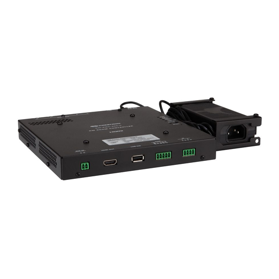
- Page 1 Crestron DM-RMC-200-C DigitalMedia 8G+™ Receiver & Room Controller 200 Operations & Installation Guide...
- Page 2 Crestron, the Crestron logo, Crestron e-Control, Crestron Toolbox, DigitalMedia, DigitalMedia 8G, DigitalMedia 8G+, DM, DM 8G, DM 8G+, and Excite are trademarks or registered trademarks of Crestron Electronics, Inc. in the United States and other countries. Dolby, Dolby Digital, and the double-D symbol are either trademarks or registered trademarks of Dolby Laboratories in the United States and/or other countries.
-
Page 3: Regulatory Compliance
Regulatory Compliance As of the date of manufacture, the DM-RMC-200-C has been tested and found to comply with specifications for CE marking and standards per EMC and Radiocommunications Compliance Labelling. Federal Communications Commission (FCC) Compliance Statement This device complies with part 15 of the FCC Rules. Operation is subject to the following conditions: (1) This device may not cause harmful interference and (2) this device must accept any interference received, including interference that may cause undesired operation. -
Page 5: Table Of Contents
Further Inquiries ......................32 Future Updates ......................33 Return and Warranty Policies ....................34 Merchandise Returns / Repair Service ..............34 CRESTRON Limited Warranty................. 34 GNU General Public License ....................35 Contents • i Operations & Installation Guide – DOC. 7126B... -
Page 7: Digitalmedia 8G+™ Receiver & Room Controller 200: Dm-Rmc-200-C
Allows adjustable overscan or underscan up to 7.5% (Continued on following page) 1. For DM 8G+ wiring up to 330 feet (100 meters) between devices, use Crestron DM-CBL-8G DigitalMedia 8G cable, Crestron DM-CBL DigitalMedia cable, Crestron DM-CBL-D DigitalMedia D cable, or generic CAT5e (or better) UTP or STP. Shielded cable and connectors are recommended to safeguard against unpredictable environmental electrical noise which may impact performance at resolutions above 1080p. - Page 8 Provides automatic 3D-to-2D conversion if display device does not support 3D. 2. Video wall processing requires a separate DM-RMC-200-C for each individual display. 3. For DM 8G+ wiring up to 330 feet (100 meters) between devices, use Crestron DM-CBL-8G DigitalMedia 8G cable, Crestron DM-CBL DigitalMedia cable, Crestron DM-CBL-D DigitalMedia D cable, or generic CAT5e (or better) UTP or STP.
-
Page 9: Audio Amplifier
AV receiver, amplifier, or sound system. 1. For DM 8G+ wiring up to 330 feet (100 meters) between devices, use Crestron DM-CBL-8G DigitalMedia 8G cable, Crestron DM-CBL DigitalMedia cable, Crestron DM-CBL-D DigitalMedia D cable, or generic CAT5e (or better) UTP or STP. - Page 10 HDMI connection, potentially eliminating the need for any dedicated control wires or IR probes. Two low-voltage relay ports are also included on the DM-RMC-200-C for control of a projection screen or lift. In addition, there are two discrete digital input ports to accommodate room occupancy sensors, power sensors, or contact closures for enhanced automation and monitoring.
-
Page 11: Applications
Applications The diagram below shows a DM-RMC-200-C in a standalone application. In this application, the DM-RMC-200-C is used with a DM 8G+ transmitter such as the DM-TX-201-C and is not used with a DM switcher. DM-RMC-200-C in a Standalone Application DigitalMedia 8G+™... -
Page 12: Specifications
DigitalMedia 8G+™ Receiver 200 Crestron DM-RMC-200-C Specifications Specifications for the DM-RMC-200-C are listed in the following table. DM-RMC-200-C Specifications SPECIFICATION DETAILS Video Scaler HD video scaler, motion-adaptive deinterlacer, interlacer, intelligent frame rate conversion, Deep Color support, 3D-to-2D conversion , content-adaptive... - Page 13 TrueHD, DTS DTS-ES, DTS 96/24, DTS-HD High Res, DTS-HD Master Audio™, up to 8ch PCM Analog Stereo 2-Channel Digital-to-Analog Conversion 24-bit 48 kHz (Continued on following page) DigitalMedia 8G+™ Receiver 200: DM-RMC-200-C • 7 Operations & Installation Guide – DOC. 7126B...
- Page 14 1.85 in (47 mm) including bracket Weight 3.3 lb (1.5 kg) including bracket and power pack Included Accessory Universal 24 Volt DC Power Pack (Continued on following page) 8 • DigitalMedia 8G+™ Receiver 200: DM-RMC-200-C Operations & Installation Guide – DOC. 7126B...
- Page 15 7. With reduced blanking only. 8. Using the DMTool in Crestron Toolbox, the amplifier can be enabled/disabled. 9. The latest software versions can be obtained from the Crestron Web site. Refer to the NOTE following these footnotes. 10. Crestron 2-Series control systems include the AV2 and PRO2. Consult the latest Crestron Product Catalog for a complete list of 2-Series control systems.
-
Page 16: Physical Description
This section provides information on the connections, controls and indicators available on your DM-RMC-200-C. DM-RMC-200-C Physical View (Front Panel View) DM-RMC-200-C Physical Views (Top Panel View) DM-RMC-200-C Physical Views (Bottom and Rear Panel View) 10 • DigitalMedia 8G+™ Receiver 200: DM-RMC-200-C Operations & Installation Guide – DOC. 7126B... - Page 17 Crestron DM-RMC-200-C DigitalMedia 8G+™ Receiver 200 DM-RMC-200-C Overall Dimensions (Front and Side Panel Views without Mounting Bracket Installed) 7.63 in (194 mm) 7.48 in (190 mm) 7.92 in 7.55 in (202 mm) (192 mm) 1.06 in (27 mm) 1.40 in...
- Page 18 DigitalMedia 8G+™ Receiver 200 Crestron DM-RMC-200-C DM-RMC-200-C Overall Dimensions (Side Panel View with Mounting Bracket Installed) 1.78 in (46 mm) 1.85 in (47 mm) DM-RMC-200-C Connectors, Controls & Indicators (Front Panel View) 12 • DigitalMedia 8G+™ Receiver 200: DM-RMC-200-C Operations & Installation Guide – DOC. 7126B...
- Page 19 Crestron DM-RMC-200-C DigitalMedia 8G+™ Receiver 200 DM-RMC-200-C Connectors, Controls & Indicators (Top Panel View) DM-RMC-200-C Connectors, Controls & Indicators (Bottom Panel View) DM-RMC-200-C Connectors, Controls & Indicators (Rear Panel View) DigitalMedia 8G+™ Receiver 200: DM-RMC-200-C • 13 Operations & Installation Guide – DOC. 7126B...
- Page 20 RX - RX + 24 V (1) 2.1 mm barrel DC power jack; 2.0A MAX 24 Volt DC power input; Power pack included (Continued on following page) 14 • DigitalMedia 8G+™ Receiver 200: DM-RMC-200-C Operations & Installation Guide – DOC. 7126B...
- Page 21 (1) 4-pin 3.5 mm detachable terminal block comprising two normally open, isolated relays; Rated 1 Amp, 30 Volts AC/DC; MOV arc suppression across contacts (Continued on following page) DigitalMedia 8G+™ Receiver 200: DM-RMC-200-C • 15 Operations & Installation Guide – DOC. 7126B...
- Page 22 Blue Brown 7. For DM 8G+ wiring up to 330 feet (100 meters) between devices, use Crestron DM-CBL-8G DigitalMedia 8G cable, Crestron DM-CBL DigitalMedia cable, Crestron DM-CBL-D DigitalMedia D cable, or generic CAT5e (or better) UTP or STP. Shielded cable and connectors are recommended to safeguard against unpredictable environmental electrical noise which may impact performance at resolutions above 1080p.
-
Page 23: Setup
The IP ID is set within the DM-RMC-200-C IP table using Crestron Toolbox™. For information on setting an IP table, refer to the Crestron Toolbox help file. The IP IDs of multiple DM-RMC-200-C devices in the same system must be unique. When setting the IP ID, consider the following: •... -
Page 24: Supplied Hardware
1. Using the four included 6-32 x 3/4” slot head screws (2009211), attach the included mounting bracket to the electrical box. 2. Ground the DM-RMC-200-C and attach the proper cables to the rear of the unit (refer to “Hardware Hookup” on page 21 for information). - Page 25 Installing the Power Pack The included mounting bracket (2029286), which is used to attach the DM-RMC-200-C to an electrical box, provides a holder for the included power pack. To install the power pack, perform the following steps (refer to the illustration on the following page): 1.
- Page 26 Phillips Head Screws (2) (Included) (2007250) Installation of the power pack in the holder is shown below. Power Pack Installed in Holder of DM-RMC-200-C Mounting Bracket 20 • DigitalMedia 8G+™ Receiver 200: DM-RMC-200-C Operations & Installation Guide – DOC. 7126B...
-
Page 27: Hardware Hookup
Make the necessary connections as called out in the following illustrations. Refer to “Network Wiring” on page 17. Apply power after all connections have been made. Hardware Connections for the DM-RMC-200-C (Top Panel View) AUDIO OUT R, L AUDIO OUT R, L... - Page 28 UTP or STP. Shielded cable and connectors are recommended to safeguard against unpredictable environmental electrical noise which may impact performance at resolutions above 1080p. Refer to the latest version of the Crestron DigitalMedia Infrastructure Guide (Doc. 4556) for complete wiring guidelines and to the Crestron DigitalMedia Design Guide (Doc.
-
Page 29: Programming Software
Have a question or comment about Crestron software? Answers to frequently asked questions (FAQs) can be viewed in the Online Help section of the Crestron Web site. To post a question or view questions you have submitted to Crestron’s True Blue Support, log in at www.crestron.com/support. - Page 30 DigitalMedia 8G+™ Receiver 200 Crestron DM-RMC-200-C The system tree of the control system displays the DM-RMC-200-C in the appropriate slot with a default IP ID as shown in the following illustrations. In the first example, the DM-RMC-200-C is used with the DMCO-50 output card in a DM-MD8X8 switcher.
- Page 31 Crestron DM-RMC-200-C DigitalMedia 8G+™ Receiver 200 C2ENET-2 Device, Slot 8 (Using Ethernet Slot on Control System) 2. If additional DM-RMC-200-C devices are to be added, repeat step 1 for each device. Each DM-RMC-200-C device is assigned a different IP ID.
- Page 32 DigitalMedia 8G+™ Receiver 200 Crestron DM-RMC-200-C Program Manager Program Manager is the view where programmers “program” a Crestron control system by assigning signals to symbols. The symbol can be viewed by double-clicking the icon or dragging it into Detail View. Each signal in the symbol is described in the SIMPL Windows help file (F1).
-
Page 33: Uploading And Upgrading
1. Establish communication between the PC and the DM switcher as described in the latest version of the DigitalMedia Switchers Operations Guide (Doc. 6755). 2. Use the Device Discovery Tool in Crestron Toolbox to find the IP address of the DM-RMC-200-C. The tool is available in Toolbox version 1.15.143 or later. - Page 34 DM 8G+ To establish USB communication between the PC and the DM switcher: 1. Use the Address Book in Crestron Toolbox to create an entry using the expected communication protocol (USB). When multiple USB devices are connected, identify the DM switcher by entering “DM-MD8X8”, “DM-MD16X16”, or “DM-MD32X32”...
-
Page 35: Firmware
For details on upgrading, refer to the Crestron Toolbox help file. Check the Crestron Web site to find the latest firmware. (New users may be required to register to obtain access to certain areas of the site, including the FTP site.) To upgrade DM-RMC-200-C firmware: 1. -
Page 36: Ip Configuration
DM switcher), use Crestron Toolbox to create the IP table entry of the DM-RMC-200-C. NOTE: If the DM-RMC-200-C is connected to a DM switcher, the IP table entry of the DM-RMC-200-C is created automatically. 1. Use the Device Discovery Tool to find the IP address of the DM-RMC-200-C. -
Page 37: Problem Solving
Crestron DM-RMC-200-C DigitalMedia 8G+™ Receiver 200 Problem Solving Troubleshooting The following table provides corrective action for possible trouble situations. If further assistance is required, please contact a Crestron customer service representative. DM-RMC-200-C Troubleshooting TROUBLE POSSIBLE CAUSE(S) CORRECTIVE ACTION PWR LED... -
Page 38: Reference Documents
Crestron Web site (www.crestron.com) for a listing of Crestron worldwide offices. You can also log onto the online help section of the Crestron Web site (www.crestron.com/onlinehelp) to ask questions about Crestron products. First-time users will need to establish a user account to fully benefit from all available features. -
Page 39: Future Updates
Crestron DM-RMC-200-C DigitalMedia 8G+™ Receiver 200 Future Updates As Crestron improves functions, adds new features and extends the capabilities of the DM-RMC-200-C, additional information may be made available as manual updates. These updates are solely electronic and serve as intermediary supplements prior to the release of a complete technical documentation revision. -
Page 40: Return And Warranty Policies
Purchasers should inquire of the dealer regarding the nature and extent of the dealer's warranty, if any. CRESTRON shall not be liable to honor the terms of this warranty if the product has been used in any application other than that for which it was intended or if it has been subjected to misuse, accidental damage, modification or improper installation procedures. -
Page 41: Gnu General Public License
You may charge a fee for the physical act of transferring a copy and you may at your option offer warranty protection in exchange for a fee. DigitalMedia 8G+™ Receiver 200: DM-RMC-200-C • 35 Operations & Installation Guide – DOC. 7126B... - Page 42 Program (or any work based on the Program), you indicate your acceptance of this License to do so and all its terms and conditions for copying, distributing or modifying the Program or works based on it. 36 • DigitalMedia 8G+™ Receiver 200: DM-RMC-200-C Operations & Installation Guide – DOC. 7126B...
- Page 43 THIRD PARTIES OR A FAILURE OF THE PROGRAM TO OPERATE WITH ANY OTHER PROGRAMS), EVEN IF SUCH HOLDER OR OTHER PARTY HAS BEEN ADVISED OF THE POSSIBILITY OF SUCH DAMAGES. DigitalMedia 8G+™ Receiver 200: DM-RMC-200-C • 37 Operations & Installation Guide – DOC. 7126B...
- Page 44 Crestron Electronics, Inc. Operations & Installation Guide – DOC. 7126B 15 Volvo Drive Rockleigh, NJ 07647 (2029414) Tel: 888.CRESTRON 07.11 Fax: 201.767.7576 Specifications subject to www.crestron.com change without notice.
Need help?
Do you have a question about the DM-RMC-200-C and is the answer not in the manual?
Questions and answers