Table of Contents
Advertisement
Quick Links
Advertisement
Table of Contents
Troubleshooting

Related Manuals for Crestron QM-RMCRX-BA


Summary of Contents for Crestron QM-RMCRX-BA
- Page 1 Crestron QM-RMCRX-BA QuickMedia™ Receiver/Processor Operations Guide...
- Page 2 This document was prepared and written by the Technical Documentation department at: Crestron Electronics, Inc. 15 Volvo Drive Rockleigh, NJ 07647 1-888-CRESTRON All brand names, product names and trademarks are the property of their respective owners. ©2005 Crestron Electronics, Inc.
-
Page 3: Table Of Contents
Communication Settings ...20 Troubleshooting Communications ...24 Identity Code...26 Earliest Version Software Requirements for the PC ...28 Configuring with Crestron SystemBuilder™ ...28 Creating a QuickMedia System in SystemBuilder...29 Audio and Video Adjustments ...32 Setting Network IDs in SystemBuilder ...36 Example Program...38 Troubleshooting ...38... -
Page 5: Quickmedia™ Receiver/Processor: Qm-Rmcrx-Ba
Features and Functions The QM-RMCRX-BA combines a Crestron system with a QuickMedia™ input (receiver) and Cresnet QM-RMCRX-BA is designed to mount at the projector or plasma display to provide local display control, LAN connectivity, and signal management. Functional Summary Operations Guide – DOC. 6332 QuickMedia™... - Page 6 The QM-RMCRX-BA then converts each of those signal types back to standard analog signals for connection to a display (projector or flat-panel monitor), an audio amplifier, or if using the on-board amplifier, directly to speakers.
- Page 7 COM ports, four digital inputs, two Cresnet ports, one IR port, and one 10/100 Ethernet port. The QM-RMCRX-BA is shipped as a master controller, but may also be used as a slave. Refer to “Master-Slave Modes” in the latest version of the Crestron 2-Series Control Systems Reference Guide (Doc.
-
Page 8: Quickmedia Transport System
Crestron RoomView™ software. Using Crestron RoomView, organizations can monitor multiple room A/V controllers on an Ethernet network, in real time, from any network PC. Crestron RoomView and the QM-RMCRX-BA can provide remote power control and management of A/V devices, including monitoring lamp life of projectors, device status to ensure proper equipment operations, room occupancy, equipment use log, and device and room security. - Page 9 VGA signals may experience a loss of quality over very long lengths of cable. This phenomenon is due to the added resistance and capacitance of longer cable lengths, and is not particular to either Crestron and/or QuickMedia systems.
-
Page 10: Display Device Selection For A Quickmedia System
Crestron database support discrete commands. Refer to the Crestron Database in System Builder or the Dealer/Tech Resources | Whose Products Do We Control? Section of the Crestron website for a list of products. You may search by manufacturer or device type. You may also call the Crestron customer service team or check our online help system for the latest information. -
Page 11: Specifications
Crestron QM-RMCRX-BA Specifications Specifications for the QM-RMCRX-BA are given in the following table. QM-RMCRX-BA Specifications SPECIFICATION Processor Speed Memory Power Usage Initial Firmware Release Default Network ID Ports/Connectors Reset Buttons Composite/S-Video RGB Video Continued on the following page 1. For more information on system memory usage, refer to “Memory” on page 13. -
Page 12: Physical Description
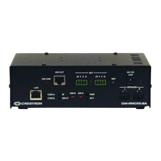
Weight Physical Description The QM-RMCRX-BA is housed in a black enclosure with labeling on the front and rear panels. There are four rubber feet on the base of the unit for stability and to prevent slippage. Refer to the following illustrations and physical views. - Page 13 Crestron QM-RMCRX-BA QuickMedia™ Receiver/Processor QM-RMCRX-BA Rear View Physical Dimensions QuickMedia™ Receiver/Processor: QM-RMCRX-BA • 9 Operations Guide – DOC. 6332...
- Page 14 This male connector can be used to supply 24 VDC power to the QM-RMCRX-BA from an external power pack (included). CAUTION: Use only Crestron power supplies for Crestron equipment. Failure to do so could cause equipment damage or void the Crestron warranty. Green Yellow An 8-position RJ-45 port (labeled LAN) is used for connection to the Ethernet, providing local area network or Web access (cable is not supplied).
- Page 15 Crestron QM-RMCRX-BA Rear Panel Ports The QM-RMCRX-BA rear panel ports are illustrated and described as follows. S-Video S-VIDEO One DIN type connector is provided for S-video output. S-video contains two separate Pin 4 Pin 3 components, luminance and chrominance (also known as Y and C signals respectively).
- Page 16 A null modem cable is required to connect to a computer. NOTE: RS-422 and RS-485 are not supported. Standard COM DB9 Pinout 12 • QuickMedia™ Receiver/Processor: QM-RMCRX-BA Crestron QM-RMCRX-BA per channel balanced, 2 V DIRECTION...
-
Page 17: Reset Buttons
ID as the QM-RMCRX-BA. Reset Buttons Two buttons are provided on the front panel of the QM-RMCRX-BA. Refer to the following descriptions. HW-R Pressing this button initiates system hardware reset. (Same effect as disconnecting and reconnecting power.) -
Page 18: Memory
Refer to the 2-Series Control Systems Reference Guide (Doc. 6256) for additional memory structure information. Industry Compliance As of the date of manufacture, the QM-RMCRX-BA has been tested and found to comply with specifications for CE marking and standards per EMC and Radiocommunications Compliance Labelling. -
Page 19: Setup
Cresnet power usage of the entire chain. If the unit is a home-run from a Crestron system power supply network port, the Cresnet power usage of that unit is the Cresnet power usage of the entire run. The length of the run in feet and the Cresnet power usage of the run should be used in the resistance equation below to calculate the value on the right side of the equation. -
Page 20: Qm Network Wiring
Repeat the procedure for the other three conductors. NOTE: For additional information on video connections over CAT5, refer to the latest version of the Crestron CAT5 Wiring Reference Guide (Doc. 6137) which is available from Crestron website (http://www.crestron.com/manuals). -
Page 21: Hardware Hookup
Crestron QM-RMCRX-BA Mounting Positions of the Four Included Mounting Brackets NOTE: The MK-QM-RMCRX mounting kit is available for mounting the QM-RMCRX-BA to a pipe. Details can be found in the latest version of the MK-QM-RMCRX Installation Guide (Doc. 6247). Hardware Hookup Refer to the following hookup diagram and, aside from attaching power last, complete the connections in any order. - Page 22 NOTE: COM B is shared for device control and serial console connection. NOTE: Use either the internal amplifier (SPEAKER) output or the AUDIO left and right line outputs, but not both. Using both induces noise. 18 • QuickMedia™ Receiver/Processor: QM-RMCRX-BA Crestron QM-RMCRX-BA Operations Guide - DOC. 6332...
-
Page 23: Ground Wire Connections
Crestron does not recommend it. NOTE: In larger system configurations that require more power than supplied by Cresnet, disconnect the +24 VDC wire from the QM-RMCRX-BA Cresnet connector and provide the +24 VDC power to the peripheral devices by an alternate Crestron power source. -
Page 24: Communication Settings
QuickMedia™ Receiver/Processor The Crestron Toolbox allows you to perform these functions using simple graphical views and click and drag methods. Communication Settings Establishing communications is an essential step when setting up the control system. Once communications are established with the control system, you can upload programming, update firmware, and use all the diagnostic tools available in Crestron Toolbox. - Page 25 Hardware handshaking (RTS/CTS) enabled. • Software handshaking (XON/XOFF) not enabled. 2. After setting the correct parameters, click OK to return to the Crestron Toolbox main window. 3. Select Tools | System Info. If the connection is successful, the window displays the Net ID and serial connection parameters in the General area of the System Info window.
- Page 26 Green Typical TCP/IP Connection – Direct PC Connection using Crossover Cable 2. Once the cable connections are made, open Crestron Toolbox. Click Tools | Manage Address book to display the “Address Book” window and enter the new address name. Then click TCP as the connection type.
- Page 27 80 = Web 41794 = Crestron Com 41795 = Toolbox/Debug 3. After setting the correct parameters, click OK to return to the Crestron Toolbox main window. 4. Select Tools | System Info. The window displays the connection parameters in the Ethernet area of the System Info window.
-
Page 28: Troubleshooting Communications
QuickMedia™ Receiver/Processor Crestron Toolbox - Text Console Open Establishing Console Mode on an Ethernet Slave Enter serial console mode by holding down the SW-R button while booting up. The COM B LED will flash to indicate console mode. Please be aware that doing this causes the processor to boot up in standalone mode, rather than Ethernet slave mode. - Page 29 “Address Book” window. Choose RS-232 as the connection type. b. Set the baud rate of the PC to 115200. Set the baud rate of the QM-RMCRX-BA control system to 115200, as follows: Press and release the HW-R button on the unit’s front panel.
-
Page 30: Identity Code
Net IDs can be changed from a personal computer (PC) using SystemBuilder or Crestron Toolbox. The Net ID of the QM-RMCRX-BA has been factory set to 02, which designates the QM-RMCRX-BA as a master control unit. In slave mode, the QM-RMCRX-BA operates as a 2-Series Cresnet or Ethernet device. - Page 31 3. Select the new Net ID from the pull-down list. Ensure that the new hardware ID agrees with the ID assigned in SystemBuilder and is not a duplicate. Cresnet Toolbox – Cresnet ID Change Window. QuickMedia™ Receiver/Processor: QM-RMCRX-BA • 27...
-
Page 32: Configuring The Qm-Rmcrx-Ba
Have a question or comment about Crestron software? Answers to frequently asked questions (FAQs) can be viewed in the Online Help section of the Crestron website. To post a question or view questions you have submitted to Crestron’s True Blue Support, log in at http://support.crestron.com. -
Page 33: Creating A Quickmedia System In Systembuilder
Crestron QM-RMCRX-BA Crestron SystemBuilder is fully integrated with Crestron's suite of software development tools, including SIMPL Windows, VT Pro-e, Crestron Database, User IR Database, and User Modules Directory. Crestron System Builder accesses these tools behind the scenes, enabling you to easily create robust systems. - Page 34 NOTE: You can select any 2-Series control processor as the master. Additional QM-RMCRX-BAs added to the system are automatically assigned a slave ID (03 and above) as they are added. 30 • QuickMedia™ Receiver/Processor: QM-RMCRX-BA Crestron QM-RMCRX-BA 2. Select the plug-in for a QuickMedia system.
- Page 35 Example – Right-Click on QM Connector 8. Build the program. The “Finish” window affords an opportunity to set/reset network IDs and verify hardware network IDs. 9. After completing your SystemBuilder program, click the Build and Upload System button QuickMedia™ Receiver/Processor: QM-RMCRX-BA • 31...
-
Page 36: Audio And Video Adjustments
(up to 40 ms of delay is permitted). Overall speech and program volume controls (0 to 100%) appear on all audio adjustment screens. 32 • QuickMedia™ Receiver/Processor: QM-RMCRX-BA Crestron QM-RMCRX-BA SystemBuilder – “Finish” Window 1. -
Page 37: Volume Settings
Crestron QM-RMCRX-BA SystemBuilder Mixer Adjustments Volume Settings Volume for speech and program are adjusted for the internal amplifier using this screen. SystemBuilder Volume Controls Operations Guide – DOC. 6332 QuickMedia™ Receiver/Processor QuickMedia™ Receiver/Processor: QM-RMCRX-BA • 33... - Page 38 QuickMedia™ Receiver/Processor Output Graphic EQ SystemBuilder provides independent graphic equalization for speech, program left and program right audio. Output Graphic EQ 34 • QuickMedia™ Receiver/Processor: QM-RMCRX-BA Crestron QM-RMCRX-BA Operations Guide - DOC. 6332...
-
Page 39: Video Settings
The first bitmap (for Steps 1 and 2) consists of lines of black text on gray and white backgrounds, and lines of blue text on gray and white backgrounds. You may also browse for your own bitmap test image. Video Settings Operations Guide – DOC. 6332 QuickMedia™ Receiver/Processor QuickMedia™ Receiver/Processor: QM-RMCRX-BA • 35... -
Page 40: Setting Network Ids In Systembuilder
Crestron QM system. NOTE: All presets are immediately stored to the QM-RMCRX-BA, even those on other screens. There is no need to explicitly save them. - Page 41 Right-click on a device in the network tree on the right and set the • Net ID directly. SystemBuilder – “Set Network ID” Window SystemBuilder detects all connected devices and displays a graphic that verifies all devices and indicates the status of the hardware and software Net IDs. QuickMedia™ Receiver/Processor: QM-RMCRX-BA • 37...
-
Page 42: Example Program
QuickMedia™ Receiver/Processor Example Program An example program for the QM-RMCRX-BA is available from the “Example Program” section of the Crestron website (http://www.crestron.com/exampleprograms). Problem Solving Troubleshooting The following table provides corrective action for possible trouble situations. If further assistance is required, please contact a Crestron customer service representative. - Page 43 QM-RMCRX-BA Troubleshooting (continued) System Monitor Mode The System Monitor allows you to reload firmware into the QM-RMCRX-BA in the event that you cannot load the firmware in the normal mode. Perform the following procedure to correct the “System does not function”...
-
Page 44: Battery Replacement
[1-888-273-7876]. For assistance in your local time zone, refer to the Crestron website (www.crestron.com) for a listing of Crestron worldwide offices. You can also log onto the online help section of the Crestron website to ask questions about Crestron products. First-time users will need to establish a user account to fully benefit from all available features. -
Page 45: Appendix A: Programming With Simpl Windows
Program Manager, for designing the logic and functionality of the control system. In addition, you can use the powerful Crestron Toolbox utility to accomplish multiple system tasks, such as uploading the program to the control system and performing diagnostic functions. - Page 46 IR emitters, splitters, receivers, and remote control transmitters may be required). No detail is required, and no symbol is shown. To add an IR device, drag the device from the Crestron, Project, or User IR Database to the C2I-RMC-IR1 port. The Crestron database contains hundreds of IR driver files, covering most IR devices on the market today.
- Page 47 NOTE: Does not support RS-422 or RS-485. NOTE: COM B cannot be used to control a device when a PC is controlling the QM-RMCRX-BA through the console on this serial port. NOTE: The [RESERVED] field is left blank. NOTE: C2N-NPA8 is not supported.
- Page 48 Device Settings. Normally this signal would not be used (If RTS/CTS is selected in the "Hardware Handshaking" options, this signal will not be driven). High/1 = CTS pin activated Low/0 = CTS pin released Continued on the following page 44 • QuickMedia™ Receiver/Processor: QM-RMCRX-BA Crestron QM-RMCRX-BA Operations Guide - DOC. 6332...
- Page 49 Slot 5: Cresnet: C2Net-Device The C2Net-Device slot enables the QM-RMCRX-BA to control up to 252 Cresnet devices. Each Cresnet device is assigned a unique identifier called a Net ID, which is a hexadecimal value ranging from 03 to FE.
- Page 50 The C2I-RXBA-VIDEO module can route any video source to the corresponding output for transmission to the display device. The QM-RMCRX-BA supports up to 254 skew presets, where a skew preset consists of three RGB skew values together with peaking and boost. Each skew preset applies to the cable connection between the QM-RMCRX-BA and a specific QM transmitter.
- Page 51 This signal has NO effect if automatic video compensation is enabled. Recalls the R/G/B skew values and peak/boost values stored in the preset given by <SkewPreset#> when the input is held high. High/1 (level sensitive) = Recall skew preset Low/0 = No preset recall QuickMedia™ Receiver/Processor: QM-RMCRX-BA • 47...
- Page 52 Analog input <Peaking> Analog output <Peaking_F> Continued on the following page 48 • QuickMedia™ Receiver/Processor: QM-RMCRX-BA Crestron QM-RMCRX-BA DESCRIPTION Enables automatic video compensation for as long as the input is high. High/1 (level sensitive) = Enable auto-compensation Low/0 = Disable auto-compensation Enables the projector filter for as long as the input is high.
- Page 53 Reports the skew preset currently being recalled. <SkewPreset#_Recalled> Slot 7: C2I-RX-MIXER The C2I-RX-Mixer module is built into slot 07 of the QM-RMCRX-BA QuickMedia control system and audio/video receiver. It provides one QM input labeled QM that receives four channels of digital audio as follows: The unit provides one 9-pin balanced/unbalanced line level audio output labeled AUDIO, with three channels labeled L, R and SPCH.
- Page 54 QuickMedia™ Receiver/Processor Crestron QM-RMCRX-BA Detail View of Audio Mixer 50 • QuickMedia™ Receiver/Processor: QM-RMCRX-BA Operations Guide - DOC. 6332...
- Page 55 Out of range values will clip the mixing level to the minimum or maximum value. Analog output Indicates the current mixing level being applied to MIC 1 on the AUDIO SPCH channel. <Mic1ToMicMixOut_F> Continued on the following page Operations Guide – DOC. 6332 QuickMedia™ Receiver/Processor QuickMedia™ Receiver/Processor: QM-RMCRX-BA • 51...
- Page 56 Out of range values will clip the mixing level to the minimum or maximum value. Analog output Indicates the current mixing level being applied to MIC 1 on the AUDIO L channel. <Mic1ToPgmLeft_F> Continued on the following page 52 • QuickMedia™ Receiver/Processor: QM-RMCRX-BA Crestron QM-RMCRX-BA Operations Guide - DOC. 6332...
- Page 57 Out of range values will clip the mixing level to the minimum or maximum value. Analog output Indicates the current mixing level being applied to MIC 1 on the AUDIO R <Mic1ToPgmRight_F> channel. Continued on the following page Operations Guide – DOC. 6332 QuickMedia™ Receiver/Processor QuickMedia™ Receiver/Processor: QM-RMCRX-BA • 53...
- Page 58 Out of range values will clip the trim to the minimum or maximum value. Analog outputs Indicates the trim being applied to each band of the MIC 1 equalizer. <Mic1EQTrim1_F> through <Mic1EQTrim4_F> Continued on the following page 54 • QuickMedia™ Receiver/Processor: QM-RMCRX-BA Crestron QM-RMCRX-BA Operations Guide - DOC. 6332...
- Page 59 The General Audio Controls module is built into slot 08 (with auto compensation). Refer to Appendix B on page 65 for additional auto compensation information. The QM-RMCRX-BA provides one QM input labeled QM that receives four channels of digital audio as follows: The unit provides the following audio outputs: The QM-RMCRX-BA supports up to 192 source gain compensation presets, which allow for normalization of audio levels between different sources.
- Page 60 Mutes the AUDIO SPCH channel for as long as the input is high. <MuteMicMixOut> High/1 (level-sensitive) = Mute AUDIO SPCH Low/0 = Un-mute audio Continued on the following page 56 • QuickMedia™ Receiver/Processor: QM-RMCRX-BA Crestron QM-RMCRX-BA Operations Guide - DOC. 6332...
- Page 61 Out of range values will clip the speech delay to the minimum or maximum value. Analog output Indicates the speech delay being applied to the AUDIO SPCH channel. <MicMixDelay-F> Continued on the following page Operations Guide – DOC. 6332 QuickMedia™ Receiver/Processor QuickMedia™ Receiver/Processor: QM-RMCRX-BA • 57...
- Page 62 Indicates the current source gain compensation. <ProgComp-F> Slot 9: C2I-RX-GRAPHICEQ The C2I-RX Graphic EQ module is built into slot 09 of the QM-RMCRX-BA QuickMedia control system and audio/video receiver. The QM-RMCRX-BA provides graphic and parametric equalization for each of the three audio output channels: Program Left, Program Right and Speech audio (Mic Mix Out).
- Page 63 Low/0 = No trim preset recall Recalls the filter preset given by <FilterPreset#> when the input is held high. (The filters are only settable using SystemBuilder software.) High/1 (level-sensitive) = Recall filter preset Low/0 = No filter preset recall QuickMedia™ Receiver/Processor: QM-RMCRX-BA • 59...
- Page 64 <AudioOut1SpTrimBand10_F> The QM-RMCRX-BA provides 10 trim presets, where a trim preset is the set of all available (maximum of 10) <TrimBand> values for the graphic EQ filters. The <TrimBand> inputs adjust the gains of the graphic EQ filters. The gains are adjustable within a range of -12dB to +12dB.
- Page 65 This is the same as recalling a trim preset in which every trim band value is set to 0. In addition to the 10 trim presets, the QM-RMCRX-BA provides five filter presets, where a filter preset is a set of six filters. A filter consists of the center frequency, gain, bandwidth and filter type (EQ, high/low pass, treble/bass shelf) for each of the three outputs channels.
-
Page 66: Converting Programs And Modules Created For Other Systems
2-Series processor requires all signal types to be strictly defined. If the program you want to convert contains SIMPL+ or User modules, Crestron recommends that you first compile each module before converting the larger program. In this way, the compiler can resolve any ambiguous signals in the modules and minimize errors when the larger program is converted. -
Page 67: Advanced Console Commands
The SIMPL Windows online help file provides a full listing of console commands that are valid for 2-Series control systems. You can access the QM-RMCRX-BA console in a variety of ways: via a serial connection (RS-232) with a PC connected to port B, over Ethernet via the LAN port, or through Telnet, among many other methods. - Page 68 NOTE: For more information on console commands, refer to the 2-Series Console Command Reference Guide (Doc. 6002). The latest version can be obtained from the Crestron website. "SIMPL Windows Preferences" Window 64 • QuickMedia™ Receiver/Processor: QM-RMCRX-BA Crestron QM-RMCRX-BA Operations Guide - DOC. 6332...
-
Page 69: Appendix B: Quickmedia Installation And Compensation
NOTE: If auto compensation is used in your QM system, all QM devices must use it. If it is not used in your QM system, it must not be used for any of the QM devices. Operations Guide – DOC. 6332 QuickMedia™ Receiver/Processor QuickMedia™ Receiver/Processor: QM-RMCRX-BA • 65... - Page 70 QuickMedia™ Receiver/Processor Auto Compensation with a Self-Peaking Receiver Crestron's innovative self-peaking audio circuit eliminates the need to peak the audio signal. Without self-peaking the same peak and boost values are applied equally to the video and audio signals. When these signals travel the same path, this arrangement is satisfactory.
-
Page 71: Compatibility Charts
MD4x2 MD7x2 MD5x1 Auto Compensation with Audio Breakaway RMCRX MD8x8 TRANSMITTERS MD4x2 MD7x2 MD5x1 Operations Guide – DOC. 6332 QuickMedia™ Receiver/Processor QM RECEIVERS RMCRX- RXA* MD7x2 QM RECEIVERS RMCRX- RXA* MD7x2 QuickMedia™ Receiver/Processor: QM-RMCRX-BA • 67 TPMC MD5x1 TPMC MD5x1... - Page 72 Manual Compensation without Audio Breakaway RMCRX MD8x8 TRANSMITTERS MD4x2 MD7x2 MD5x1 Manual Compensation with Audio Breakaway RMCRX MD8x8 TRANSMITTERS MD4x2 MD7x2 MD5x1 68 • QuickMedia™ Receiver/Processor: QM-RMCRX-BA QM RECEIVERS RMCRX- RXA* MD7x2 QM RECEIVERS RMCRX- RXA* MD7x2 Crestron QM-RMCRX-BA TPMC MD5x1 TPMC MD5x1...
-
Page 73: Software License Agreement
Agreement, which shall remain valid and enforceable according to its terms. This Agreement may only be modified by a writing signed by an authorized officer of Crestron. Updates may be licensed to You by Crestron with additional or different terms. This is the entire agreement between Crestron and You relating to the Software and it supersedes any prior representations, discussions, undertakings, communications or advertising relating to the Software. - Page 74 Crestron or its authorized agents of the Software that deviates from any operating procedures established by Crestron in the material and files provided to You by Crestron or its authorized agent; (3) use of the Software on unauthorized hardware;...
-
Page 75: Return And Warranty Policies
CRESTRON shall not be liable to honor the terms of this warranty if the product has been used in any application other than that for which it was intended, or if it has been subjected to misuse, accidental damage, modification, or improper installation procedures. - Page 76 Crestron Electronics, Inc. Operations Guide – DOC. 6332 15 Volvo Drive Rockleigh, NJ 07647 (2011912) Tel: 888.CRESTRON 05.05 Fax: 201.767.7576 Specifications subject to www.crestron.com change without notice.
Need help?
Do you have a question about the QM-RMCRX-BA and is the answer not in the manual?
Questions and answers