Table of Contents
Advertisement
Quick Links
Advertisement
Table of Contents
Troubleshooting

Related Manuals for Crestron QM-RMCRX


Summary of Contents for Crestron QM-RMCRX
- Page 1 Crestron QM-RMCRX QuickMedia™ Receiver/Processor Operations Guide...
- Page 2 This document was prepared and written by the Technical Documentation department at: Crestron Electronics, Inc. 15 Volvo Drive Rockleigh, NJ 07647 1-888-CRESTRON All brand names, product names and trademarks are the property of their respective owners. ©2004 Crestron Electronics, Inc.
-
Page 3: Table Of Contents
Future Updates ...36 Programming with SIMPL Windows...37 Compiling and Uploading a Program to the Control System ...48 Uploading Web pages to the QM-RMCRX ...49 Converting Programs and Modules Created for Other Systems...50 Updating the Operating System ...52 Advanced Console Commands ...53 Merchandise Returns / Repair Service ...56... -
Page 5: Quickmedia™ Receiver/Processor: Qm-Rmcrx
SIMPL+ • Two bi-directional COM ports (RS-232 only). • One IR port - compatible with Crestron ST-SPL IR-Splitter, for IR- Control of up to five different devices, programmable via the hundreds of IR device drivers available in the Crestron database. - Page 6 QM-RMCRX. Video signals received by the QM-RMCRX are applied to the display device via the RGBHV, S-video, and composite video ports. Each video output port is switched for signal selection to match the selected input source of the QuickMedia transmitter (sold separately).
- Page 7 COM ports, four digital inputs, two Cresnet ports, one IR port, and one 10/100 Ethernet port. The QM-RMCRX is shipped as a master controller, but may also be used as a slave. Refer to the latest version of the Crestron 2-Series Control Systems Master-Slave Mode Reference Guide (Doc.
- Page 8 QuickMedia™ Receiver/Processor The QM-RMCRX provides an integrated Web server with SSL, allowing users to control AV devices from any computer on the LAN, WAN, or even custom web pages designed using Crestron VisionTools e-Control 2 XPanel technology, Web pages have the same look and feel as TPS touchpanel pages, with the same outstanding runtime performance.
-
Page 9: Display Device Selection For A Quickmedia System
Products Do We Control? section of the Crestron website (www.crestron.com) for a list of products. You may search by manufacturer or device type. You may also call the Crestron customer service team or check our online help system for the latest information. -
Page 10: Specifications
QuickMedia™ Receiver/Processor Specifications Specifications for the QM-RMCRX are given in the following table. QM-RMCRX Specifications 1. For more information on system memory usage, refer to “Memory” on page 12. 2. For more information on controls, ports, and indicators, refer to the following “Physical Specifications continued on next page 6 •... -
Page 11: Physical Description
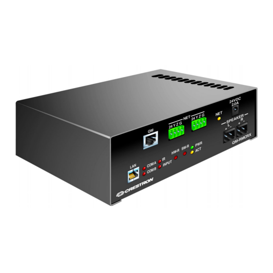
QM-RMCRX Specifications (continued) Physical Description The QM-RMCRX is housed in a black enclosure with labeling on the front and rear panels. There are four rubber feet on the base of the unit for stability and to prevent slippage. Refer to the following illustrations and physical views. -
Page 12: Front Panel Ports
Physical Dimensions (19.13 cm) Front Panel Ports The QM-RMCRX front panel ports are illustrated and described as follows. QM Input Eight-pin RJ-45 QuickMedia transport port. Accepts CAT5E audio, video, microphone, and control signals. The QM input port conforms to the 568B wiring standard. - Page 13 QM-RMCRX from an external power pack (included). CAUTION: Use only Crestron power supplies for Crestron equipment. Failure to do so could cause equipment damage or void the Crestron warranty. An 8-position RJ-45 port (labeled LAN) is used for connection to the Ethernet, providing local area network or Web access (cable is not supplied).
- Page 14 NOTE: Some DLP display devices are extremely sensitive to noise. The anti- aliasing filter included with the QM-RMCRX may be used at the RGBHV output or on the display device input. Crestron QM-RMCRX...
- Page 15 This green LED illuminates when the unit is connected to and receives 24 VDC power from an external power pack or from Cresnet. ACT (LAN) This yellow LED illuminates when the QM-RMCRX communicates with any device on the network. Operations Guide – DOC. 6236A QuickMedia™...
-
Page 16: Reset Buttons
ID as the QM-RMCRX. Reset Buttons Two buttons are provided on the front panel of the QM-RMCRX. Refer to the following descriptions. HW-R Pressing this button initiates system hardware reset. (Same effect as disconnecting and reconnecting power.) - Page 17 Operations Guide – DOC. 6236A QuickMedia™ Receiver/Processor SECONDARY DESCRIPTION LEVEL LEVEL Root of the file system DISPLAY Legacy directory used in Crestron Isys panels to hold display lists Contains various system configuration files SETUP Contains web-based setup pages HTML Web pages SIMPL...
-
Page 18: Industry Compliance
If the unit is a home-run from a Crestron system power supply network port, the power factor of that unit is the power factor of the entire run. -
Page 19: Quickmedia Wiring
QuickMedia CAT5E wiring. QuickMedia Wiring The Crestron QuickMedia cable (sold by Liberty Wire and Cable under the name “CRESCAT-QM”) contains one CAT5E cable and one Cresnet siamese jackets. Installation of any QuickMedia device is as simple as installing one set of QuickMedia wires from input to output. -
Page 20: Mounting
The total accumulated skew from source to receiver must not exceed 15 ns (nanoseconds). Crestron recommends a cable rating of 15 ns per 100 m (328 ft.). -
Page 21: Hardware Hookup
Mounting Positions of the Four Included Mounting Brackets 4.56 in (11.58 cm) NOTE: The MK-QM-RMCRX mounting kit is available for mounting the QM- RMCRX to a pipe. Details can be found in the latest version of the MK-QM- RMCRX Installation Guide (Doc. 6247). - Page 22 Using both induces noise. NOTE: Proper grounding is required. Connect the ground wires from the QM transmitter (QM-WMC/QM-WMIC) to earth ground. Connect the Cresnet shield at the QM-RMCRX to the chassis ground provided on the QM-RMCRX. The 18 • QuickMedia™ Receiver/Processor: QM-RMCRX ETHERNET:...
-
Page 23: Power Supply
Crestron QM-RMCRX QM-RMCRX chassis must also be connected to an earth ground (building steel). Refer to the following grounding diagram. Grounding Diagram Power Supply The QM-RMCRX can be powered through the NET network connector, or by the external PW-2420 power pack (60W) included but not by both methods. -
Page 24: Serial Connection
All of these functions are accesse through the commands and options in the Viewport menus. Therefore, for its effectiveness as a support and diagnostic tool, the Crestron Viewport may be preferred over development tools when uploading programs and projects. -
Page 25: Tcp/Ip Connection
For TCP/IP, use CAT5 straight through cables with 8-pin RJ-45 connectors to connect the LAN port on the QM-RMCRX and the LAN port on the PC to the Ethernet hub. Alternatively, you can use a CAT5 crossover cable to connect the two LAN ports directly, without using a hub. - Page 26 QuickMedia™ Receiver/Processor RJ-45 Pinouts Once the cable connections are made, open the Crestron Viewport and click Setup | Communication Settings on the menu to display the “Port Settings” window. Then click TCP/IP as the connection type. Enter the IP address of the QM-RMCRX.
-
Page 27: Troubleshooting Communications
If the connection is successful, both the PC and the control system will be set to the new baud rate. The QM-RMCRX will return to its original communication settings when the program reinitializes. -
Page 28: Identity Code
Windows program. In slave mode, the QM-RMCRX operates as a 2-Series control system Cresnet or Ethernet device. For example, the QM-RMCRX can be part of a larger master control system that includes: audio and video switching, IR and relay control, and Ethernet, using touchpanels to operate the QM-RMCRX slave through the master 2-Series control system. -
Page 29: Configuring The Qm-Rmcrx
First-time users will need to establish a user account. Use the Crestron programming tools Crestron SystemBuilder™ and Crestron Digital Media Tools™ to create a control program for the QM-RMCRX control system. The higher level of SIMPL Windows flexibility requires a much greater degree of programming expertise and is not recommended for this application. -
Page 30: Configuring With Crestron Systembuilder
Configuring with Crestron SystemBuilder NOTE: The QM-RMCRX is configured with Crestron SystemBuilder version 1.0 software. As of press time, this version of Crestron SystemBuilder had not been released. Please check the Crestron FTP site. The Crestron SystemBuilder interface guides you through a few basic steps for specifying the control system, designating rooms and touchpanels, devices, and functionality. - Page 31 Video Options – Choose how the sources will be connected to the system and choose automatic system power on/off options. • Power Control – Use this window to setup power control for the display device. QuickMedia™ Receiver/Processor: QM-RMCRX • 27...
-
Page 32: Digital Media Tools
Add additional interfaces (keypads, touchpanels, etc.) • Add additional devices and A/V sources • Modify the sequences • Modify the home page through VisionTools Pro-e ® programs for configuring high quality audio. Crestron makes it easy Crestron QM-RMCRX Operations Guide - DOC. 6236A... - Page 33 Crestron QM-RMCRX The QM-RMCRX Digital Media Tools adjustment contains the following nine tabs. When using the second setup procedure that includes the QM-WMIC, an additional tab is used to adjust microphone gain, noise gating, attack and decay, and also provides a real-time audio monitor.
-
Page 34: Video Adjustments
"white streaking" and you need to decrease the peaking value. If you see "blooming" or pixel areas that appear larger than normal, you need to decrease the gain. 30 • QuickMedia™ Receiver/Processor: QM-RMCRX Crestron QM-RMCRX Operations Guide - DOC. 6236A... - Page 35 Crestron QM system. NOTE: All presets are immediately stored to the QM-RMCRX, even those on other screens. There is no need to explicitly save them.
-
Page 36: Problem Solving
(ftp://ftp.crestron.com/Examples). Search for: QM-RMCRX. Problem Solving Troubleshooting The following table provides corrective action for possible trouble situations. If further assistance is required, please contact a Crestron customer service representative. QM-RMCRX Troubleshooting Troubleshooting continued on following page 32 • QuickMedia™ Receiver/Processor: QM-RMCRX... -
Page 37: System Monitor
QM-RMCRX Troubleshooting (continued) System Monitor The System Monitor allows you to reload firmware into the QM-RMCRX in the event that you cannot load the firmware in the normal mode. Perform the following procedure to correct the “System does not function”... -
Page 38: Battery Replacement
“Set Baud Rate” window. Battery Replacement A Lithium battery is used to power the system clock within the QM-RMCRX. Under normal conditions, it lasts for approximately 10 years. In the event that the clock fails, only an authorized technician should replace it. Refer to the following caution statement. -
Page 39: Further Inquiries
Further Inquiries If after reviewing this Operations Guide, you cannot locate specific information or have questions, please take advantage of the Crestron award winning customer service team by calling: Operations Guide – DOC. 6236A QuickMedia™... -
Page 40: Firmware Upgrades
Firmware Upgrades To take advantage of all the QM-RMCRX features, it is important that the unit contains the latest firmware available. Therefore, please check the Crestron website (http://www.crestron.com/downloads/software_updates.asp) for the... -
Page 41: Appendix: Simpl Windows Programming
Program Manager, for designing the logic and functionality of the control system. In addition, you can use the powerful Crestron Viewport utility to accomplish multiple system tasks, such as uploading the program to the control system and performing diagnostic functions. - Page 42 IR emitters, splitters, receivers, and remote control transmitters may be required). To add an IR device, drag the device from the Crestron, Project, or User IR Database to the C2I-RMC-IR1 port. The Crestron database contains hundreds of IR driver files, covering most IR devices on the market today. The IR port requires one IRP2 (infrared emitter probe) installed on each IR device.
- Page 43 The card provides 252 IP IDs for Ethernet devices. Slot 5: Cresnet: C2Net-Device The C2Net-Device slot enables the QM-RMCRX to control up to 252 Cresnet devices. Each Cresnet device is assigned a unique identifier called a Net ID, which is a hexadecimal value ranging from 03 to FE.
- Page 44 Cresnet device, expand C2Net-Device in Program View. Then drag the device to Detail View. Slot 6: C2I-RX-VIDEO The built-in video output control module enables the QM-RMCRX to select video outputs, compensate for signal attenuation, and save and recall up to 100 skew presets for transmitting nodes.
- Page 45 Media Tools software while viewing the video test patterns. The explanations presented here are for completeness of information. The QM-RMCRX supports up to 100 skew presets for video. These presets are programmable using Crestron Digital Media Tools (DMT) software or SIMPL Windows.
- Page 46 QuickMedia™ Receiver/Processor QM-RMCRX Audio Architecture The QM-RMCRX provides five mixer presets, where a mixer preset consists of the four mixing levels (program right, program left, QM Mic 1, and QM-Mic 2) for each of the three outputs. Mixing levels are adjustable from -80dB to 0dB;...
- Page 47 Similarly, when the <RecallMixerPreset> input is driven high, the mixing levels stored in <MixerPreset#> will be recalled and immediately propagated to the outputs. Here the <F> feedback signals may have different values than their corresponding inputs. Operations Guide – DOC. 6236A QuickMedia™ Receiver/Processor QuickMedia™ Receiver/Processor: QM-RMCRX • 43...
- Page 48 -800. In addition to the five mixer presets, the QM-RMCRX provides ten mic EQ presets for the Mic1 and Mic2 inputs, where a Mic EQ preset is the set of all eight <MicEQTrim>...
- Page 49 <SaveCompPreset> and <RecallCompPreset> are used to save and recall the input compensation presets. The QM-RMCRX provides four independent audio inputs (via the CAT5 QM port): Program Left, Program Right, Mic1 and Mic2. The onboard mixer can mix any audio input into any of the three independent audio outputs: Program Left, Program Right and Speech Audio (Mic Mix Out).
- Page 50 The analog <F> feedback signals report the current volume and delay values for each output. Slot 9: C2I-RX-GRAPHICEQ The C2I-RX Graphic EQ module is built into slot 09 of the QM-RMCRX QuickMedia control system and audio/video receiver. The QM-RMCRX provides graphic and parametric equalization for each of the three audio output channels: Program Left, Program Right and Speech Audio (Mic Mix Out).
- Page 51 Crestron QM-RMCRX Detail View of Graphic Equalization Module The QM-RMCRX provides 10 trim presets, where a trim preset is the set of all available (maximum of 10) <TrimBand> values for the graphic EQ filters. The <TrimBand> inputs adjust the gains of the graphic EQ filters. The gains are adjustable within a range of -12dB to +12dB.
-
Page 52: Compiling And Uploading A Program To The Control System
Compiling and Uploading a Program to the Control System After you have completed your SIMPL Windows program for the QM-RMCRX, you must compile and upload the program to the control system. To compile the program, simply click the Convert/Compile button SIMPL Windows toolbar, or select Project | Convert/Compile (you can also press F12). -
Page 53: Uploading Web Pages To The Qm-Rmcrx
XPANEL. In designing and creating a browser project, keep in mind that you must assign an IP ID to all the project pages and specify the IP address of the QM-RMCRX. Operations Guide – DOC. 6236A QuickMedia™ Receiver/Processor... -
Page 54: Simpl Windows
As with all Ethernet devices, the PC Interface must receive an entry in the IP Table of the QM-RMCRX. Here the IP ID must match the IP ID that was assigned in VT Pro-e, while the IP address must be set to a loopback: 127.0.0.1, when hosting internal. - Page 55 Crestron QM-RMCRX If the program you want to convert contains SIMPL+ or User modules, Crestron recommends that you first compile each module before converting the larger program. In this way, the compiler can resolve any ambiguous signals in the modules and minimize errors when the larger program is converted.
-
Page 56: Updating The Operating System
SIMPL Windows online help file. Updating the Operating System As with all 2-Series control systems, operating system files for the QM-RMCRX have a .cuz extension. You can obtain .cuz updates (when available) from the Downloads | Software Updates section of the Crestron website. -
Page 57: Advanced Console Commands
Viewport menus. NOTE: For more information on console commands, refer to the 2-Series Console Command Reference Guide (Doc. 6002). The latest version can be obtained from the Downloads | Product Manuals section of the Crestron website (www.crestron.com). "SIMPL Windows Preferences" Window Operations Guide –... -
Page 58: Software License Agreement
Agreement, which shall remain valid and enforceable according to its terms. This Agreement may only be modified by a writing signed by an authorized officer of Crestron. Updates may be licensed to You by Crestron with additional or different terms. This is the entire agreement between Crestron and You relating to the Software and it supersedes any prior representations, discussions, undertakings, communications or advertising relating to the Software. - Page 59 Crestron or its authorized agents of the Software that deviates from any operating procedures established by Crestron in the material and files provided to You by Crestron or its authorized agent; (3) use of the Software on unauthorized hardware;...
-
Page 60: Return And Warranty Policies
CRESTRON shall not be liable to honor the terms of this warranty if the product has been used in any application other than that for which it was intended, or if it has been subjected to misuse, accidental damage, modification, or improper installation procedures. - Page 61 Crestron QM-RMCRX QuickMedia™ Receiver/Processor This page intentionally left blank. QuickMedia™ Receiver/Processor: QM-RMCRX • 57 Operations Guide – DOC. 6236A...
- Page 62 QuickMedia™ Receiver/Processor Crestron QM-RMCRX This page intentionally left blank. 58 • QuickMedia™ Receiver/Processor: QM-RMCRX Operations Guide - DOC. 6236A...
- Page 63 Crestron QM-RMCRX QuickMedia™ Receiver/Processor This page intentionally left blank. QuickMedia™ Receiver/Processor: QM-RMCRX • 59 Operations Guide – DOC. 6236A...
- Page 64 Crestron Electronics, Inc. Operations Guide – DOC. 6236A 15 Volvo Drive Rockleigh, NJ 07647 06.04 Tel: 888.CRESTRON Fax: 201.767.7576 Specifications subject to www.crestron.com change without notice.
Need help?
Do you have a question about the QM-RMCRX and is the answer not in the manual?
Questions and answers