Table of Contents
Advertisement
Quick Links
Top Flite Models Champaign, IL
Ph: (217) 398-8970, Ext. 5
Fax: (217) 398-7721
airsupport@top-flite.com
WARRANTY
®
Top Flite
Model Manufacturing Co. guarantees this kit to be free from defects in both material and
workmanship at the date of purchase. This warranty does not cover any component parts damaged by use
or modification. In no case shall Top Flite's liability exceed the original cost of the purchased kit.
Further, Top Flite reserves the right to change or modify this warranty without notice.
In that Top Flite has no control over the final assembly or material used for final assembly, no liability shall be
assumed nor accepted for any damage resulting from the use by the user of the final user-assembled
product. By the act of using the user-assembled product, the user accepts all resulting liability.
If the buyer is not prepared to accept the liability associated with the use of this product, the buyer is
advised to return this kit immediately in new and unused condition to the place of purchase.
To make a warranty claim send
the defective part or item to
Hobby Services at this address:
Include a letter stating your name, return shipping address, as much contact information as possible (daytime
telephone number, fax number, e-mail address), a detailed description of the problem and a photocopy of the
purchase receipt. Upon receipt of the package the problem will be evaluated as quickly as possible.
READ THROUGH THIS MANUAL BEFORE STARTING CONSTRUCTION. IT CONTAINS IMPORTANT INSTRUCTIONS AND WARNINGS CONCERNING THE ASSEMBLY AND USE OF THIS MODEL.
Entire Contents © 2012 Hobbico, Inc.
Hobby Services
3002 N. Apollo Dr. Suite 1
Champaign IL 61822 USA
Technical Assistance Call
(217) 398-8970
productsupport@top-flite.com
INSTRUCTION
MANUAL
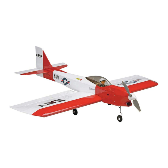
SPECIFICATIONS
Wingspan:
36 in [915 mm]
Wing Area:
329 sq in [ 21.2 dm
Weight:
27– 30 oz [ 765 – 850 g]
Wing
11.8 – 13.1 oz/sq ft
2
Loading:
[36 – 40 g/dm
]
Length:
34.5 in [875 mm]
Radio:
4 channel
Motor:
RimFire .10
TOPA1025 Mnl
2
]
Advertisement
Table of Contents

Related Manuals for Top Flite Mini Contender Ep


Summary of Contents for Top Flite Mini Contender Ep
- Page 1 Further, Top Flite reserves the right to change or modify this warranty without notice. Wing Area: 329 sq in [ 21.2 dm In that Top Flite has no control over the final assembly or material used for final assembly, no liability shall be Weight: 27– 30 oz [ 765 – 850 g] assumed nor accepted for any damage resulting from the use by the user of the final user-assembled product.
-
Page 2: Table Of Contents
For the latest technical updates or manual corrections 6. While this model has been fl ight tested to exceed to the Mini Contender EP ARF visit the Top Flite web normal use, if the plane will be used for extremely Or via the Internet at: http://www.modelaircraft.org... -
Page 3: Decisions You Must Make
❍ AccuThrow ™ Defl ection Gauge (GPMR2405) POWER RECOMMENDATIONS that are required to fi nish the Mini Contender EP ARF ❍ CG Machine™ (GPMR2400) The plane has been designed to use the RimFire .10, ❍ 1/2 oz. [15g] Thin Pro ❍... -
Page 4: Model Inspection
Fx: (217) 398-7721 E-mail: airsupport@top-fl ite.com ORDERING REPLACEMENT PARTS Replacement parts for the Top Flite Mini Contender EP ARF are available using the order numbers in the Replacement Parts List that follows. The fastest, most economical service can be provided by your hobby dealer or mail-order company. -
Page 5: Assemble The Wing
ASSEMBLE THE WING of thin CA in each screw hole. After the CA has cured, reinstall the aileron servo and screws. ❏ ❏ 2. Carefully pull the string from the aileron servo opening and tie it to the end of the servo extension. ❏... -
Page 6: Install The Main Landing Gear
INSTALL THE MAIN LANDING GEAR ASSEMBLE THE FUSELAGE INSTALL THE STABILIZER ❏ ❏ ❏ 1. Remove the two elevator halves from the 9. Enlarge the outer hole of the nylon control horn horizontal stabilizer. Insert the elevator joiner wire in to 5/64"... -
Page 7: Install The Servos
center the servo arms. The rudder needs to have a two arm servo arm for the rudder and the nose steering. Insert the two 17-1/2" [435mm] long metal pushrods in the rudder and elevator outer pushrod tubes. Align the rudder and elevator servos so that the pushrods are aligned with the holes in the servo arms 1/4"... -
Page 8: Install The Nose Gear
❏ ❏ ❏ 4. Install the 1-5/8" [40mm] long metal pushrods in 2. Slide a 1/8" [3mm] wheel collar and 4-40 x 1/8" 4. Install the foam nose wheel on the nose gear the elevator and rudder servo arms. Center the rudder [3 mm] machine screw onto the nose gear wire. -
Page 9: Install The Cowl
INSTALL THE COWL ❏ ❏ 2. Mount the plywood motor mount to the front of the 1. Tape a piece of paper to both sides of the fuselage, ❏ fuselage with four 2-56 x 3/8" [10mm] machine screw 4. Before you install the receiver in the ESC/receiver even with the fi... -
Page 10: Apply The Decals
5. The recommended pilot will require some trimming damage the receiver. to fi t in the cowl. We used a piece of scrap wood to make a base on which to mount the pilot. We use a Top Flite Precision Magnetic Prop Balancer FULL ELEVATOR THROTTLE... -
Page 11: Balance The Model (C.g.)
These are the recommended control surface throws: HIGH RATE LOW RATE LESS Pushrod Farther Out THROW 3/8" 1/4" Up and Up and [10 mm] [6 mm] Down Down 11° 7° 1-1/8" 3/4" Right Right [29mm] [19 mm] Pushrod Closer In &... -
Page 12: Check List
❏ 4. IMPORTANT: If you found it necessary to add 2-5/16" [ 59 mm] any weight, recheck the C.G. after the weight has 2-5/16" been installed. [59mm] CHECK LIST During the last few moments of preparation your mind may be elsewhere anticipating the excitement of the fi... -
Page 13: Preflight
● The motor may get hot! Do not touch it right after before every fl ight. With computer radios it is easy to CAUTION: Unless the instructions that came with mistakenly change the model. operation. your radio system state differently, the initial charge ❏... -
Page 14: Radio Control
fl utter can actually cause Take it easy with the Mini Contender EP ARF for the the control surface to detach or the fl ying surface 3) At all fl ying sites a straight or curved line(s) must be fi... - Page 15 in certain conditions (such as on high or low rates). This is not necessarily to improve your skills (though it is never a bad idea!), but more importantly so you do not surprise yourself by impulsively attempting a maneuver and suddenly fi nding that you’ve run out of time, altitude or airspeed.
Need help?
Do you have a question about the Mini Contender Ep and is the answer not in the manual?
Questions and answers