Table of Contents
Advertisement
Quick Links
WARRANTY.....
not cover any component parts damaged by use or modification. In no case shall Top Flite's liability exceed the original cost of the purchased kit. Further, Top Flite reserves
the right to change or modify this warranty without notice. In that Top Flite has no control over the final assembly or material used for final assembly, no liability shall be
assumed nor accepted for any damage resulting from the use by the user of the final user-assembled product. By the act of using the user-assembled product the user
accepts all resulting liability. If the buyer is not prepared to accept the liability associated with the use of this product, the buyer is advised to immediately return this kit in
new and unused condition to the place of purchase.
Top Flite Models P.O. Box 788 Urbana, Il 61803
READ THROUGH THIS INSTRUCTION BOOK FIRST. IT CONTAINS IMPORTANT INSTRUCTIONS AND WARNINGS CONCERNING THE ASSEMBLY AND USE OF THIS MODEL.
Entire Contents © Copyright 1999
Top Flite Models guarantees this kit to be free of defects in both material and workmanship at the date of purchase. This warranty does
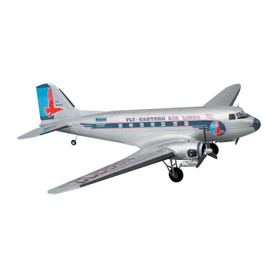
Wingspan: 82-1/2" [2095 mm]
Wing Area: 750 sq. in. [48.4 sq. dm]
Weight: 8 - 10 Lbs. [3629 - 4536g]
Wing Loading: 24.6 - 30.7 oz./sq. ft. [75 - 94 g/sq. dm]
Fuselage Length: 55.5 in. [1410 mm]
Technical Assistance Call (217)398-8970 productsupport@top-flite.com
™
DC3TP03
V1.1
Advertisement
Table of Contents

Related Manuals for Top Flite Douglas DC-3


Summary of Contents for Top Flite Douglas DC-3
- Page 1 In no case shall Top Flite‘s liability exceed the original cost of the purchased kit. Further, Top Flite reserves the right to change or modify this warranty without notice. In that Top Flite has no control over the final assembly or material used for final assembly, no liability shall be assumed nor accepted for any damage resulting from the use by the user of the final user-assembled product.
-
Page 2: Table Of Contents
Sheet the top of the fuselage ........24 ENGINE SAFETY PRECAUTIONS ......64 Build the bottom of the fuselage.......26 Your Top Flite Gold Edition DC-3 is intended for AMA SAFETY CODE ..........65 Install the pushrods ..........26 scale and general sport flying including mild FLYING ...............65... -
Page 3: Precautions
(217) 398-8970 or e-mail Your DC-3 is designed to incorporate scale split flaps; Your Top Flite Gold Edition DC-3 will perform well with us at productsupport@top-flite.com and we’ll be however, flaps are optional and not necessary for an any of the engines within the recommended range, but glad to help. -
Page 4: Scale Rudder
Edition DC-3 is 1:14, or one-fourteenth scale. information on the use of the flaps in the Flying section. The Top Flite DC-3 is a sport scale model of the Douglas If you plan to enter your DC-3 in scale competition (it’s lots DC-3. -
Page 5: Other Items Required
Other than engine-out flying characteristics, there are a the Hobbico brand. Fortunately, the Top Flite DC-3 flies so well with an engine few other flight qualities you should be aware of. The out that you do not need to make any immediate control... -
Page 6: Die-Cut Patterns
DIE-CUT PATTERNS - 6 -... -
Page 7: Die-Cut Patterns
DIE-CUT PATTERNS - 7 -... -
Page 8: Building Supplies
Easy–Touch ™ Bar Sanders* through to the end before you begin. Frequently there We also use Top Flite 320-grit (TOPR8030, 4 sheets) Dremel ® #178 cutting bit for countersinking screws is important information or a note at the end of the step... -
Page 9: Get Ready To Build
15" = 381mm 3/16" = 4.8mm 18" = 457.2mm 1/4" = 6.4mm 21" = 533.4mm Top Flite selects balsa that is intended for sheeting, 3/8" = 9.5mm 24" = 609.6mm though occasionally a few of these sheets may have 1/2" = 12.7mm 30"... - Page 10 so it will be large enough to make a stab skin. After the glue dries cut the skin slightly larger than the pattern to allow some room for positioning. Make another stab skin the same way. F. Place weights on top of the sheets to hold them down ( see page 12 on how to make weight bags ).
-
Page 11: Build The Stabilizer
BUILD THE STABILIZER 7. Glue rib S1 to the rudder torque rod block using two more rib jigs to hold it in place like you did with the other ribs. 1. Cut the stab plan along the dashed line and tape it to your building board. -
Page 12: Build The Elevators
resin to glue the skin to the ribs and CA to glue the skin to 16. Sheet the bottom of the stab with the other stab the TE, LE and tips. Wet the outside of the sheeting in the skin you prepared. Use care not to add any twist to the middle near the leading edge. - Page 13 not directly on top of the line. Use a square to make sure you glue the LE perpendicular to the elevator core. Hint: Place a 1/4" piece of balsa under the square to raise it to the level of the LE. 3.
-
Page 14: Build The Fin And Rudder
14. Test fit the hinges into the slots. If the hinges do elevators to the stab with the joiner wire and the hinges. IMPORTANT NOTES ABOUT CA HINGES not slide into the slots easily, work your knife blade back Note that the horn on the joiner wire points downward. and forth in the slot a few times to provide more Cut a small notch in the TE of the stab for the horn on the This kit is supplied with a CA hinge material... - Page 15 3. The same way you did for the stab, use your 1/4" x 7. If you haven’t yet done so, cut out your fin skins. 14. Tack glue the rudder LE, centered, to the fin TE 5/16" rib jigs to hold the balsa fin ribs V1 through V7 Sheet the left side of the fin with one of your fin skins with about four small drops of medium CA.
- Page 16 1. Cut the scale fin and rudder plan along the dashed line and tape it to your building board. Cover the plan DC-3 Fact with Plan Protector. By the late 20's the air transportation industry was rapidly expanding with small airline companies springing up everywhere.
- Page 17 5. The same way you did for the stab, use your 1/4" x 5/16" rib jigs to hold the fin ribs V1 through V7 over their location on the plan. Use a square to align the ends of the ribs with the TE on the plan. 8.
- Page 18 21. Place approximately 1/32" shims from cardstock or something similar between the forward rudder LE sections and the fin TE section. Carefully view the structure, making sure everything is in alignment, and glue the forward rudder LE sections to the ply rudder hinges and glue the aft rudder LE sections to the rudder core, hinge guides, and rudder hinges.
- Page 19 photo. Be careful not to get any glue between the fin 28. Add the 1/16" and 3/32" balsa rudder ribs to the hinge and the rudder hinges and don’t glue the rudder rudder. Sand the ribs to match the cross section on the sheeting to the fin sheeting.
-
Page 20: Build The Fuselage
rudder base block shown on the plan. Fill the space BUILD THE FUSELAGE between the base block and the bottom rudder ribs with leftover 1/16" balsa. FRAME THE FUSELAGE TOP 1. If you haven’t already done so, tape the left fuse 37. - Page 21 centerline connecting both punch marks on one side of F12 (this will be the front) and horizontal guidelines 1/16" above and below the punch marks on the other side of F12 (this will be the back). For illustration purposes the photo shows two F12's. Disregard the shape of F12 in the following photos until you get to step three on page 25.
-
Page 22: Mount The Stab And Fin
3/16" x 3/16" x 30" balsa stringer so it fits the LE of the x 10" pieces to fit the aft end of the fuse so it matches stab as shown in the photo (from here forward, all 3/16" the stab saddle and glue it in place. Note that this aft x 3/16"... - Page 23 8. If you haven’t already done so, final-sand the stab before you glue it to the fuse. It’s easier to do when it’s off the fuse than when it is glued in place! Don’t sand the mark off the top of the stab near the TE indicating the center. 5.
-
Page 24: Sheet The Top Of The Fuselage
15. Now that you are sure the stab will align, remove it 19. Test fit the fin and rudder to the stab with the Now let’s sheet the top of this thing and get it off your and apply 30-minute epoxy to the joining areas and glue torque rod. - Page 25 4. Refer to the photo that follows. Cut the stab/fin filler pattern from the plan and use it to cut two stab/fin filler sheets from a 3/32" x 3" x 30" balsa sheet. Cut the filler sheets slightly oversize to allow for trimming and fitting. 5.
-
Page 26: Build The Bottom Of The Fuselage
INSTALL THE PUSHRODS DC-3 Fact It was not long before the U.S. military became interested in the DC-1. The Army Air Corps had a need for a modern cargo/troop transport aircraft. Although impressed with the DC-1 after test pilots put it through its paces, the military opted to wait for the improved DC-2 before placing orders. - Page 27 9. Cut the .074" x 12" wire pushrod to a length of 4-1/2". Silver solder a brass threaded coupler onto this wire. Screw a nylon clevis about 12 turns onto the wire pushrod. Join the threaded coupler to the pushrod you prepared in the previous step with a nylon dual ended ball link.
-
Page 28: Finish The Bottom Of The Fuselage
of the horn on the elevator joiner wire. Move the elevator up 19. Glue the guide tube holders to the formers where and down and make sure you can get all the throw shown on the plan so the guide tubes align with the servos. recommended on page 62 of the manual. - Page 29 these stringers are installed one at a time in two layers and the uppermost stringer (nearest the main stringer) extends to F6. Trim the front of the stringers even with F1. Don’t be concerned with the stringers of the aft left side of the fuse, we’ll get to them later.
-
Page 30: Mount The Aft Hatch
14. Sheet the other side of the fuse the same way 18. Now that the fuselage is fully sheeted (except for with another 3/32" x 3" x 36" balsa sheet. the hatch on the bottom at the aft end of the fuse), use a razor plane to trim the main sub stringers even with the fuse sides. -
Page 31: Fit The Cabin Top
aft cabin former F3C to the bottom aft cabin former on our prototype (shown in the photo). When it’s time F3C. From now on this is F3C. Position F3C on top of to install the windows (after you paint the cabin top), the cabin crutch against former F3 and shape so it is you can carefully glue them in place with a small about 1/32"... -
Page 32: Build The Dorsal Fin And Fit The Tail Cone
8. Final shape the nose block and blend it to the BUILD THE DORSAL FIN AND fuselage with progressively finer grits of sandpaper. You FIT THE TAIL CONE can see the final shape of the nose cone on the plan and in photos throughout the rest of the manual. -
Page 33: Build The Wing
landing gear rail on the four die-cut 1/8" plywood wing ribs W3 and both inboard and both outboard nacelle sides. The notch in the top of the template is for retracts (R) and the notch in the bottom of the template is for fixed gear (F). - Page 34 16. Gather both die-cut 1/8" balsa center TE spars. Refer to the center TE spars on the plan. Cut both ends of one of the center TE spars to accommodate the dihedral joiner as shown on the plan. Glue the two center TE spars together so the notches align.
- Page 35 22. Position the center section assembly over the plan. Use T-pins to hold the ribs down to your building board over their locations on the plan, or use balsa jig sticks leftover from building the tail to hold the ribs over the plan the same way you did for the stab.
-
Page 36: Build The Outer Panels
BUILD THE OUTER PANELS 10. With all the parts accurately aligned over the plan, glue the spar web to the bottom spar. Glue the ribs to the spar web. Start with the left panel first so yours will look like the photos. -
Page 37: Join The Outer Panels To The Center Section
bottom of the LE as necessary at ribs 11, 12 and 13 so MOUNT THE ENGINE NACELLES you can center the LE vertically on the front of the ribs. Remember, steps that start with “R” are for retract Glue the LE to the wing ribs, centered, as indicated in builders only. -
Page 38: Mount The Retracts
Remember, steps that are shaded and start with an 7. Glue the other nacelle to the center section the R1. Fit but do not glue the 1/2" x 3/4" x 3-1/2" “F” are for fixed gear only. same way. Don’t forget to confirm that your nacelle basswood aft landing gear rail in the notches of ribs sides are in the correct location so the firewall has W3 on the left side of the center section. - Page 39 R12. Glue the aft landing gear rail and the servo hatch rails in place. R13. Notch the 1/8" x 1-5/16" x 2-13/16" plywood forward landing gear rail web as required so the air cylinder pushrod will not interfere with the web when you fit it in position where shown on the plan.
-
Page 40: Build The Fixed Landing Gear
location of the holes. Drill 1/8" holes at the marks you F1. Glue the 1/2" x 3/4" x 3-1/2" basswood aft made and insert 4-40 blind nuts (not included) into the landing gear rail in the notches of ribs W3 on the left basswood stick on the back of the rail web. - Page 41 F8. Place the landing gear alignment pattern on F11. Enlarge the threaded holes in two 5/32" wheel F13. Drill 5/32" (or #22) holes through forward the plan over your building board and cover it with Plan collars with a 5/32" drill. Slide the wheel collars onto the landing gear rail and torque blocks for the front struts.
-
Page 42: Prepare The Bottom Of The Wing For Sheeting
F23. Remove any residual soldering flux from the the firewall and the hole you previously drilled in the landing gear. You may paint the landing gear or coat it center spar web, making sure the guide tube won’t with a fine film of houshold oil to protect it from rusting. interfere with the retracts. -
Page 43: Make The Wing Skins
DC-3 Fact The 2,000 th C-47 Skytrain rolled out of the Long Beach, California plant on October 2, 1943. Determined to make this occasion a spectacular one, Joe Messick, the Public Relations Manager for Douglas, decided it would be good publicity and boost employee morale if he were to autograph the fuselage for everyone to see. -
Page 44: Build The Flaps
BUILD THE FLAPS Perform step 3 only if you are building working flaps. 3. Place the bottom center flap skin over the plan and mark the location of the flap ribs. Cut the flap LE from a Follow these instructions even if you are not 1/4"... -
Page 45: Mount The Servos In The Wing
hinges. Test the movement of the flap and make sure 15. Glue the joiner tubes to the flap with a dab of everything works. Nice isn’t it! medium CA. Actuate the flaps once again to check for smooth operation. Glue pieces of leftover 3/32" balsa to Skip step 10 if you are building working flaps. - Page 46 first because there’s only one place you can mount them mounting screws on your flap servo (so you will be able (which is determined by the hole in the hatch covers). to unscrew the screws and remove your servos later if Whatever room left is for the throttle servo.
-
Page 47: Prepare The Wing For The Top Sheeting
3. Make two fuel tank hooks by bending both 1/16" x 4" wires as shown in the sketch located on the wing plan. 9. Connect your servo extension cords and 14. Mount your aileron servos to the hatches with Y-connectors to the servos and route them through the 5/16"... -
Page 48: Sheet The Top Of The Wing
SHEET THE TOP OF THE WING your fuel lines in the wing so you will be able to retrieve leaving the corners round for a finished appearance. Use them after you glue the sheeting in place. Cut holes in the caution to avoid cutting the servo cords and fuel lines. - Page 49 6. After you have carefully set the angle and location 11. Use a razor plane or a hobby knife with a of the aileron core, glue it to the aileron LE. Glue a small carving blade to roughly shape the wing tip. section at a time using your straightedge across the bottom to make sure it remains at the correct angle.
-
Page 50: Hookup The Flaps And Ailerons
Okay, back to the ailerons... DC-3 Fact 16. Carefully break the left aileron free from the wing. In 1942 the Civilian Aviation Agency stated it would revoke the airworthiness certification of the 17. Mark the centerline on the LE of the aileron DC-3 by 1948, but the transports were “grand using the T-pin and straightedge method we showed fathered in”... -
Page 51: Sheet The Nacelles
SHEET THE NACELLES formers as necessary for the aft strut. Make a small passage for the strut from leftover 1/16" balsa. Some of the steps and photos in this section apply only to the fixed landing gear and some apply only to retract builders. - Page 52 17. Determine where to position the three 1/2" x 21. Sand the stringers and formers so they blend. 1/2" x 1-1/16" basswood cowl mounting posts (refer to the photo at step 5 on page 54). You must locate them where they will not interfere with the needle valve, muffler, fuel lines or engine.
-
Page 53: Mount The Cowls
MOUNT THE COWLS F26. Glue the skin to the nacelle formers. It’s easiest to glue the sheeting to the wing first, then bend and glue it to the formers. Trim as necessary so the front landing gear strut and the landing gear straps will fit. 1. - Page 54 5. Mount your engine to one of the nacelles (we did 8. Remove the cowl. Drill 3/32" holes in the cowl at the 10. Make a fuel filler mount from leftover 1/8" the right side first). If necessary, trim part of the cowl marks you made.
-
Page 55: Final Construction
5. Use the pin-and-string technique to align the wing FINAL CONSTRUCTION 7. Take the wing off the fuse. Tap threads in the wing the same way you did the stab, only this time stick the bolt block with a 1/4-20 tap. Saturate the threads in the T-pin in the center of the fuselage at the rear. -
Page 56: Mount The Fuel Tanks And Receiver
4. Turn the fuselage over and remove the wing. Keep the fillets. Sand the aft end of the balsa flush with the track of any pieces of balsa you may have used for fuse. Finish the aft tip of the fillet by blending the balsa shims so you can put them back in position when you and plastic to the fuselage with filler. -
Page 57: Prepare The Model For Covering
1/4" foam underneath. 9. Cut a hole in the bottom of the receiver compartment If you plan to cover your model with Top Flite for the receiver antenna. Put a strain relief on the antenna MonoKote film and you will be using Top Flite and route it out the bottom of the wing. -
Page 58: Balance The Airplane Laterally
Use a glove to avoid burning you fingers. 4. Use a large brush, compressed air or a Top Flite Tack Cloth to remove dust from the model. 2. We recommend that you prime the plastic wing 7. -
Page 59: Covering Sequence
COVERING SEQUENCE on a coat of primer. We used Top Flite LustreKote for Important: If you are using aluminum paint (as we everything that needed to be painted or fuel proofed. did on our prototype), do not sand the paint before After the primer dries, sand with 400-grit. -
Page 60: Finishing Touches
TEMPORARY PIN TO KEEP HINGE CENTERED THE CA WICKS ALONG THE "TUNNELS" TO THE ENTIRE HINGE SURFACE 4. Cut a paper towel into approximately 2" squares. Add six drops of thin CA to the center of the hinges on both the top and bottom. The tunnels you drilled will wick the CA into the entire hinge surface. -
Page 61: Panel Lines
There are two methods for adding place your Robart Incidence Meter on top of the thrust panel lines. The first method is to use a Top Flite Panel platform. Read the outward thrust. This should be 4 degrees (if your work surface is level). -
Page 62: Final Hookups And Checks
inches so you can see where to lift the wing when it’s CONTROL SURFACE THROWS bolted to the fuse. To do this, mark the balance point with a felt tip pen or tape on both ends of the center 4-CHANNEL RADIO SETUP NOTE: Throws are measured at the widest part of section. -
Page 63: Preflight
We also recommend same channel as your slave (channel seven in this We use a Top Flite Precision Magnetic Prop Balancer ™ you refer to the owners manual that came with your case). -
Page 64: Find A Safe Place To Fly
FIND A SAFE PLACE TO FLY 14. Make sure any servo extension cords you may CHECK LIST have used do not interfere with other systems The best place to fly your model is an AMA chartered During the last few moments of preparation your mind (servo arms, landing gear, pushrods, etc.). -
Page 65: Ama Safety Code
Use a chicken stick or electric starter and follow the 7. I will not fly my model unless it is identified with my down slightly and land just the same as you would with instructions to start your engines. name and address or AMA number, on or in the model. any other model. -
Page 66: Flight
Due to the small amount of prop times and decide whether or not you will be using flaps If you enjoyed building the Top Flite DC-3, try one of blast over the rudder, you will not begin to realize for your first landing. - Page 67 (TOPA0130) Top Flite AT-6 Texan (TOPA0135) Top Flite P-47D Thunderbolt 69" Wingspan, 7.5–10 Lbs. 63" Wingspan, 8.5-10.5 Lbs. (TOPA0120) Top Flite P-40E Warhawk (TOPA0300) Top Flite Cessna 182 Skylane 64" Wingspan, 8–10.5 Lbs. 81" Wingspan, 10-12 Lbs. - 67 -...
- Page 68 2-VIEW DRAWING Use this layout for trim scheme planning only. Not suitable for scale documentation.
Need help?
Do you have a question about the Douglas DC-3 and is the answer not in the manual?
Questions and answers