Top Flite P-51D Mustang User Manual
Hide thumbs
Also See for P-51D Mustang:
- User manual (60 pages) ,
- Manual (32 pages) ,
- Instruction manual addendum (4 pages)
Table of Contents
Advertisement
Quick Links
WARRANTY.....
material and workmanship at the date of purchase. This warranty does not cover any component parts
damaged by use or modification. In no case shall Top Flite's' liability exceed the original cost of the
purchased kit. Further, Top Flite reserves the right to change or modify this warranty without notice.
In that Top Flite has no control over the final assembly or material used for final assembly, no
liability shall be assumed nor accepted for any damage resulting from the use by the user of the final
user-assembled product. By the act of using the user-assembled product the user accepts all resulting
liability.
If the buyer is not prepared to accept the liability associated with the use of this product, he
is advised to immediately return this kit in new and unused condition to the place of purchase.
READ THROUGH THIS INSTRUCTION BOOK FIRST. IT CONTAINS IMPORTANT INSTRUCTIONS AND WARNINGS CONCERNING THE ASSEMBLY AND USE OF THIS MODEL.
Top Flite Models guarantees this kit to be free of defects in both
Top Flite Models
P.O. Box 788
Urbana, IL 61801
Technical Assistance - Call (217)398-8970
TM
P516P03
V1.0
Advertisement
Table of Contents

Related Manuals for Top Flite P-51D Mustang


Summary of Contents for Top Flite P-51D Mustang
- Page 1 This warranty does not cover any component parts damaged by use or modification. In no case shall Top Flite's' liability exceed the original cost of the purchased kit. Further, Top Flite reserves the right to change or modify this warranty without notice.
-
Page 2: Table Of Contents
TABLE OF CONTENTS METRIC CONVERSION CHART ....2 Operational Flaps ........46 INTRODUCTION........3 FINISHING..........49 METRIC CONVERSIONS Precautions ..........3 Final Sanding ........49 DIE PATTERNS ........4,5 Fuel Proofing ........49 Balancing the Plane Laterally ....49 1” = 25.4 mm (conversion factor) DECISIONS YOU MUST MAKE EARLY IN THE BUILDING SEQUENCE ....6 Covering ..........49 Engine and Mount Selection....6... -
Page 3: Introduction
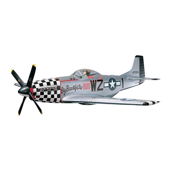
R/C pilot . Please inspect all parts carefully before The Top Flite P-51D is an excellent sport starting to build! If any parts are missing, scale model that is just as “at home” with sport broken or defective, or if you have any flying as it is in competition. -
Page 4: Die Patterns
DIE-CUT PATTERNS - 4 -... - Page 5 DIE-CUT PATTERNS BIRCH PLY BIRCH PLY - 5 -...
-
Page 6: Decisions You Must Make Early In The Building Sequence
13/64”, 1/4”, 5/64" & 17/64” The Mustang will fly well with any of the a servo or a 3/8” air cylinder and add a pull-pull Sealing Iron (Top Flite) recommended engines. The 4-cycle engines tail wheel steering system to your model. -
Page 7: Other Items Required
3/32” (2.4mm) Wheel Collars (2 for tail wheel) the aircraft takes off. This fact means that the rigid Top Flite Super MonoKote (2 rolls) Aluminum plus Red, White, Black, and Olive Drab shown ®... -
Page 8: Get Ready To Build
3. Bob Violett Models has offset door hinges BUILD THE TAIL SURFACES that are excellent for hinging inner main landing gear doors. They also offer small scale-looking 1. Work on a flat surface over the plans air cylinders that are specifically designed for covered with waxed paper. - Page 9 5. Starting with the right half of the stab, pin 9. Trim the LE and TE so they end exactly ribs S-2 and S-6 to the building board over their over the stab centerline. locations on the plans. 12. Trim the length of the die-cut 1/8” plywood Stab Joiner (SJ), if required, for a good fit between the S-2’s.
- Page 10 wipe the joint with a fresh paper towel to remove excess glue and make sanding easier. Mark the poorest surface that you think should be the inside of the sheet with an “I”. 4. Working on a flat surface, sand the skin with a large flat sanding block and fresh, sharp 220 paper.
-
Page 11: Build The Fin
Tips. Use a razor plane and a sanding block to 21. It is important to get a good glue bond shape them to match the stab airfoil. You may between the stab structure and the bottom stab contour the tip to its final shape now, or wait until skins. -
Page 12: Build The Rudder
2. Draw a centerline on the aft surface of the LE. Draw two parallel lines 1/16” away from both 12. If you are adding scale balance tabs, add sides of the centerline. 5. Glue the two 1/2” thick shaped balsa the simple additional structure as shown in the Rudder Tips to both sides of the top of the photo. -
Page 13: Build The Wing
the two die-cut 1/8” plywood Aileron Bellcrank 1. Place the wing plan on your building board Plates (AB). Assemble the bellcrank parts as and cover it with waxed paper (you may wish to shown in the sketch, making a left and a right cut the wing panel sections of the plan apart to plate. - Page 14 Glue the aileron Trailing Edge assembly to the aft edge of ribs W-8 through W-12. The upward facing edges of the ribs and the Trailing Edges should be even and the jig 12. Glue the lower 1/8” x 1/8” x 21” balsa tabs should all be touching the work surface Flap LE into the aft portion of the slots in ribs W- 8.
- Page 15 Flap TE to ribs W-2 and W-7. The flap TE shaped balsa Leading Edge to allow it to “bend” should be centered on the aft edges of the ribs (break) at R-4. Use the LE detail drawing on the and should protrude straight back (see the cross- wing plan for reference.
- Page 16 27. Sight down the wing trailing edge to make sure it is still straight. Shim any low jig tabs 21. If you are going to use flaps, trim the 24. If you plan to use flaps, fit and glue in if required.
- Page 17 bellcrank. Feed the wire assembly into the wing and screw the threaded end well into the clevis. Hint: The wire is extra long. After the threaded end starts threading into the clevis, you may bend DO STEPS 32 AND 33 IF YOU ARE BUILDING over the excess wire and use it as a handle to OPERATING FLAPS.
-
Page 18: Join Thewing Panels
spacing is not correct (it should be for most retracts) adjust the aft slots. 37. Manually extend and retract the gear, noting the strut angle. Adjust the depth of the slots if necessary to give a satisfactory angle when the gear is retracted and extended. It will be necessary to cut a slot in R-3 for the strut to pass through. - Page 19 sure all the front edges are aligned. Use a 90 9. When the wing fits on the Jig Blocks with deg. triangle to hold each W-1B/C vertical while the Aft Cross Brace (CB) and the two equal you glue it to the servo tray. length sticks in place, it is time to glue it together.
- Page 20 Make shear webs for the aft spar between F-1 and F-2. Glue them to the front of the aft spar with medium CA. 20. Trim the length of the 1/4” plywood beveled edge Wing Bolt Plate until it fits between the two W-2’s near their centerline.
-
Page 21: Sheet The Wing
SHEET THE WING 1. Sort through the remaining 1/16” x 3” x 36” wing sheeting. Pick out the best 8 sheets and set them aside for the top of the wing. fuselage plan for the proper orientation of the angle on the front of the W-1A’s. Fit this forward assembly between the two W-2’s. - Page 22 NOTE: This is a somewhat unique way NOTE: All balsa sheeting will usually 9. Cut the skin to the shape you marked. of joining the sheeting in the center of bend when it is cut from the log Check the fit of the skin to the structure and make the wing that eliminates the need for because stresses are relieved.
- Page 23 16. Apply the other bottom wing skin. wing that are not covered by the main skin. 17. If you are using functioning flaps, put light marks on the skins where the hinges will go, so you can find the blocks later. NOTE: Leave the wing on the jig until pushrods to exit the bottom wing skins.
- Page 24 taper of the ailerons over the plans to make sure 24. Working rapidly, put a stream of medium you have the correct parts. CA on each rib at the spar and allow it to run forward down the rib to the leading edge. Put a bead of medium CA on the spar.
-
Page 25: Build The Fuselage
4. Inspect the two fuselage sides. Choose the Right and Left sides so the best surfaces will BUILD THE FUSELAGE face outward. Mark the inside of the appropriate part RI and LI (for Right Inside and Left Inside.) Sand the outside (and to a lesser extent the inside) of each side with a sanding block and sharp 220 paper to smooth out the joints and the surface. - Page 26 Tape the Fuselage Bottom View over your flat 11. Drill 3/16” holes through the punch marks building board (we recommend cutting that in formers F-5, F-7, F-8, F-9, F-10, and F-11. part of your plan loose to make it easier to These holes are for the pushrod mounting, and handle).
- Page 27 F-8C to the Aft face of the former F-8A. The 1/4” 14. Place the die-cut 1/8” plywood former F-3 holes should line up. This assembly is now called in its slot but do not glue it yet since its forward F-8.
-
Page 28: Tips For Silver Soldering
21. Drill 5/64” holes through the two punch marks in the die-cut 1/8” plywood Tail Wheel E. Heat the metal with a soldering gun or iron, Plate (TW). and apply solder to the metal. The metal must get hot enough to melt the solder and the solder must freely flow into the joint. - Page 29 29. Roughen the tubular Nylon Bearing on the tail wheel wire with sandpaper so glue will stick to it. Threaded Both End Rod. Place a brass Threaded Coupler over the unthreaded end of the 8” piece. Measure the length of the Adjust the wheel collar height for best alignment assembly.
- Page 30 41. Work a lightly sanded 17-1/4” long Outer Pushrod Tube through the formers around the wire, starting at F-7 and ending at F-10. Glue the outer pushrod tube to formers F-7, F-8, and F-9, but not F-10. 36. Make sure the fuse is centered over the 39.
- Page 31 fuselage as shown. Notice on the plans (sideview) that they stop 1/2” short of the aft end of the fuselage sides. Glue them in place. 48. Test fit the die-cut 1/8” balsa Radiator Keels into the slots in F-8, F-9, and F-10. You may be required to shorten them slightly.
-
Page 32: Mount The Wing To The Fuselage
54. Roughly shape the Radiator Corners with a knife and a razor plane. Save the final shaping until after the aft bottom sheeting has been 60. Glue the two 3/4” x 2-5/8” x 4-3/8” shaped applied. balsa Chin Block pieces together as shown. The angled end of the block aligns as a projection of 57. - Page 33 5. Tape some scrap 1/32” plywood (from the wing fillet base die-cut sheet) to the wing skin 2. Round the ends of the 2-1/2” long 1/4” near the trailing edge and over the spar to Dowels. Insert the Dowels into the wing (do not simulate the die-cut plywood Fillet Base being in glue yet).
-
Page 34: Attach The Stab And Fin
3. Use a sharp knife to cut a slot in the stab ATTACH THE STAB AND FIN skin between the two S-1 stab ribs and between the marks. Cut the same slot in the bottom skin. 9. Drill through the two holes in the Wing Bolt 1. - Page 35 in the stab. Shave the sides of the LE slightly as 9. Insert the pushrod assembly into the outer needed. tube that was previously installed in the fuselage. 12. Tack glue the stab on with medium CA and again check its alignment. Glue the stab to the saddle from the inside and outside of the fuselage with 30 minute epoxy.
-
Page 36: Prepare The Elevators
14. Check the alignment of the fin from the 6. Tape both elevators to the stab. Carve front and rear of the model to see if it is vertical. and sand the tips so they conform nicely to the Glue it in with thin and medium CA. Apply some 4. -
Page 37: Fuselage Completion
4. Drill a 5/32” hole for the tail gear wire to FUSELAGE COMPLETION exit the aft fuse bottom. This hole may have to be enlarged slightly. Test fit and adjust the balsa sheet. 1. Drill a 5/32” hole through the punch mark in the die-cut 1/8”... - Page 38 NOTE: The same offset line is used, whether or not spacers are used, since the 9mm plywood engine mount spacers project at the same angle as a longer engine does. The bolt pattern in the firewall for the mounting of a shorter engine/mount combination can be laid out by putting the mount centerlines on the firewall offset line...
- Page 39 13. Mark the locations of the mounting bolts 16. This is a good time to do additional fuel 21. Cut the two Forward Deck pieces out of for your engine mount. You may find it proofing inside the nose section. the 1/8”...
-
Page 40: Install The Dorsal Fin
INSTALL THE DORSAL FIN NOTE: A few early P-51D’s did not have a Dorsal Fin. If you have a particular plane/trim scheme in mind, check to see if it has a dorsal fin. 27. True up the top of the aft deck sheeting and 3/16”... -
Page 41: Make The Top Cowling
MAKE THE TOP COWLING NOTE: The sequence below shows the installation of an O.S. .120 Surpass 4C pumper on a J-Tec JT-122SV soft mount. See the fuselage plan for an alternate engine installation. 4. Fit the balsa pieces on both sides of the Dorsal Fin. - Page 42 6. Trim the shaped 1/2” balsa Cowl Sides so they fit between the fuselage sides and the Spinner Ring. The bottom edges of the sides should align with the bottom edge of the Spinner 9. Carefully cut the corners at an angle with a 11.
-
Page 43: Mount The Cowling
3. Tape the cowl to the fuselage and put 8. Mount the cowl and finish shaping the marks on the fuselage to indicate where the nose and chin of the fuselage to blend into the mounting blocks need to go. cowl properly. - Page 44 2. Tape the plywood wing fillet pieces to the wing saddle as shown in the photographs. Notice how the Wing Fillet pieces overlap the wing saddle and fit around the fuselage behind the wing saddle. 6. Glue the long strip in place starting in the 4.
-
Page 45: Install The Forward Wing Fairing
3. Glue F-3C to the wing with medium CA. 4. Cut the 1/16” sheet balsa for the fairing using the approximate pattern provided on the shape the fillet. Remove the wing and clean up fuselage plan sheet. Test fit and trim the sheet 8. -
Page 46: Fit The Radiator
FIT THE RADIATOR NOTE: You may glue the scoop on now with CA or epoxy, fillet it in, and finish it with the rest of the airplane. However, the easiest thing to do, as done on the prototypes, is to paint the scoop separately and glue it on after the rest of the model is finished. - Page 47 NOTE: Be sure to maintain the hinge locations while shaping the flap components. 4. Use a Dremel Moto Tool with a drum 2. Cut the flap loose using a razor saw and a sander or sandpaper wrapped around a dowel to sharp knife.
- Page 48 11. Trace the outline of the Flap Servo Bay Cover accurately onto the wing skin. Carefully cut out the rest of the bay and fit the cover into place. NOTE: Unless you have a reverse throw servo, you will need to mount the flap servos in an asymmetrical 8.
-
Page 49: Finishing
Now that you have the basic airframe nearly NOTE: The hinge points are glued in completed, this is a good time to balance the after finishing. We recommend airplane laterally (side-to-side). Here is how to roughening them with grit do it: sandpaper then gluing them in with epoxy. -
Page 50: Apply Trim
The TRIM section contains information on Recommended Covering Sequence: some non-aluminum colored sections of the model. You may wish to read it before 1. Tail Fillet Strips as described in above note proceeding with the Covering section. 2. Rudder left side (black) 3. -
Page 51: Exhaust Stacks
EXHAUST STACKS 4. Repeat these divisions on the fuselage’s 2. Thoroughly clean your airplane before left and right sides as well as the bottom. applying decals. 5. Draw rings around the nose of the plane with the marker (and a pencil on the cowling). 3. -
Page 52: Final Control Hardware Hookup
FINAL CONTROL HARDWARE HOOKUP linkages. Two .074 x 12” Threaded End Rods 4. The retract air valve, tank, and servo are provided to make the flap pushrods. The flap installation can be seen in the photos above and pushrods may be connected to the servos using below. -
Page 53: Mount The Landing Gear
2. Plug in the bent wire main landing gear. 3. Mark and drill mounting holes for your retracts. 3. Hold the flat Nylon Straps in place as shown on the plans. Mark the hole locations. 4. You may make wheel well liners from 4. -
Page 54: Install Receiver, Switch And Battery
INSTALL RECEIVER, SWITCH AND 4. Paint the interior of the cockpit. An BALANCE YOUR MODEL BATTERY alternative to paint is to cover the inside of the cockpit with a fine grit black sandpaper for a NOTE: This section is VERY important Wrap your receiver and battery in plastic textured finish. -
Page 55: Final Hookups And Checks
snappier “feel” and often improves knife-edge capabilities. In any case, do not balance your FINAL HOOKUPS AND CHECKS model outside the recommended range. CONTROL SURFACE THROWS: 1. Make sure the control surfaces move in the proper direction as illustrated in the following We recommend the following control surface sketches: 2. -
Page 56: Pre-Flight
for at least two tanks of fuel. Follow the engine spectators away from the plane of rotation of the manufacturer’s recommendations for break-in. propeller as you start and run the engine. PRE-FLIGHT Check to make sure that all screws remain tight, Keep items such as these away from the that the hinges are secure and that the prop is on prop: loose clothing, shirt sleeves, ties, scarfs,... -
Page 57: Radio Control
Speed is the key to good knife- pushrod in guide tube caused by tight The Top Flite P-51D is a great flying sport edge performance. bends; sloppy fit of Z-bend in servo arm;... -
Page 58: View Drawings
TWO-VIEW DRAWING Use this layout for trim scheme planning only. Not suitable for scale documentation.
Need help?
Do you have a question about the P-51D Mustang and is the answer not in the manual?
Questions and answers