Top Flite F4U Corsair Instruction Book
Gold edition
Hide thumbs
Also See for F4U Corsair:
- Instruction book (62 pages) ,
- User manual (48 pages) ,
- Instruction manual (36 pages)
Table of Contents
Advertisement
WARRANTY.....
material and workmanship at the date of purchase. This warranty does not cover any component parts
damaged by use or modification. In no case shall Top Flite's liability exceed the original cost of the
purchased kit. Further, Top Flite reserves the right to change or modify this warranty without notice.
In that Top Flite has no control over the final assembly or material used for final assembly, no
liability shall be assumed nor accepted for any damage resulting from the use by the user of the final
user-assembled product. By the act of using the user-assembled product, the user accepts all
resulting liability.
If the buyer is not prepared to accept the liability associated with the use of this product, the
buyer is advised to immediately return this kit in new and unused condition to the place of purchase.
READ THROUGH THIS INSTRUCTION BOOK FIRST. IT CONTAINS IMPORTANT INSTRUCTIONS AND WARNINGS CONCERNING THE ASSEMBLY AND USE OF THIS MODEL.
Entire Contents © Copyright 2002
Top Flite Models guarantees this kit to be free of defects in both
Top Flite Models
P.O. Box 788
Urbana, Il 61803
Technical Assistance - Call (217) 398-8970
www.top-flite.com
™
CRS6P03 V3.0
Advertisement
Table of Contents

Related Manuals for Top Flite F4U Corsair


Summary of Contents for Top Flite F4U Corsair
- Page 1 ™ WARRANTY..Top Flite Models guarantees this kit to be free of defects in both material and workmanship at the date of purchase. This warranty does not cover any component parts damaged by use or modification. In no case shall Top Flite’s liability exceed the original cost of the purchased kit.
-
Page 2: Table Of Contents
Introduction..........3 Wing Structure Completion ....14 Cockpit Finishing.........38 Precautions ..........3 Wing Sheeting........15 Retracts Notes ........39 Die-Cut Patterns .......4-5 Fuselage Top........19 Cooling Notes ........40 Fuselage Bottom .........22 Control Surface Throws ......40 Decisions You Must Make Early in the Wing Mounting........26 Install Receiver, Switch & Battery ..40 Building Process ........6 Stab &... -
Page 3: Introduction
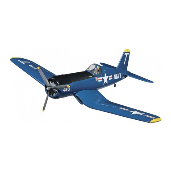
Do not alter or modify the model, as doing so may result in an unsafe or unflyable The Top Flite F4U Corsair is a sport scale model of Your Top Flite F4U Corsair is not a toy, model. In a few cases the plan and instructions the Chance Vought F4U Corsair. -
Page 4: Die-Cut Patterns
DIE-CUT PARTS... - Page 5 DIE-CUT PARTS...
-
Page 6: Decisions You Must Make Early In The
DECISIONS YOU MUST MAKE FULL COCKPIT SUPPLIES AND TOOLS NEEDED (Optional) EARLY IN THE ❏ BUILDING SEQUENCE You must decide before you build the fuselage if 2 oz. Thin CA Adhesive (GPMR6003) ❏ you will be adding the optional full cockpit kit 2 oz. -
Page 7: Other Items Required
❏ OTHER ITEMS REQUIRED Silicone Fuel Tubing (GPMQ4131) ❏ Plastic Pilot: Williams Bros. Standard, 2" Scale ❏ Four-Channel Radio with 4 servos (additional #176 (WWII Military Style) (WBRQ2476) channels and servos required if retracts and/or ❏ Main Gear Retracts (optional)...Robart #615 flaps are used). -
Page 8: Build The Fin
❏ 11. Glue on the top stab skin with medium or slow CA. Be sure to apply glue to all ribs as well as the LE and TE. ❏ 12. True the stab tips to match the die-cut stab skins. ❏... -
Page 9: Build The Rudder
BUILD THE RUDDER ❏ 1. Trim the grooved 1/2" x 1/2" balsa LE (left over from the elevators) to the length shown on the plan. Cut the balance tab LE from the 1/4" x 1/2" stock. ❏ 2. Join the 3/32" die-cut balsa rudder pieces, rudder front and rudder back together with CA. -
Page 10: Build The Wing
❏ ❏ BUILD THE WING 4. Clean up the edges of the spar with 8. Drill 3/16" holes through all ribs and doublers sandpaper. If you will be installing retracts, you that require them for aileron linkage routing. These may want to cut any holes required for your holes are located by punch marks in the ribs just WING CENTER SECTION retracts in the spar at this time. - Page 11 the main spar to match the strut cutout in (SD). The notch will probably need to be deepened slightly during final retract fitting. Keep this cut smoothly radiused to prevent the creation of a weak spot in the wing. A small Dremel ®...
-
Page 12: Tip Panels
❏ ❏ ❏ ❏ F. Disassemble the parts and enlarge the hole 23. Remove the LG assemblies and apply a 3. Cut a 1/16" slot in the 3/32" balsa die-cut drilled in the previous step in the 1/8" plate to 1/8" small fillet of 30-minute epoxy to all joints involving ribs T-4 and T-5 between the punch marks for clearance. -
Page 13: Wing Joining
❏ ❏ ❏ ❏ 6. Notch the inner end of the shaped LE and 12. Glue the bellcrank assembly securely in TE stock to match the plan. place through the slots in ribs T-4 and T-5. ❏ ❏ 7. Glue the TE to the ribs. Notice that T-7 is glued flush with the top (toward plan) edge of the TE. -
Page 14: Wing Structure Completion
❏ ❏ not to alter the shape of the ribs during this process 2. Cut a 20" piece of inner pushrod tube and (masking tape can be used to help protect them). screw a 1" piece of threaded rod and a nylon clevis Final shaping can be done after wing joining. -
Page 15: Wing Sheeting
❏ 9. In preparation for wing skinning, sand any parts that protrude higher than the surrounding parts. Any high spots will cause you to sand through the wing skins after they are applied. It is important to have a consistent structure if you want a smooth skin. - Page 16 REPEAT STEPS 5 to 9 the photos in this section...when making the skins FOR THE OTHER TIP PANEL with angled grain, cut the sheets at 45 degree angles to conserve wood. The grain direction shown ❏ ❏ 10. Cut the top outer panel wing skins from 2 for these wing skins represents the best technique remaining blanks made earlier.
- Page 17 NOTE 2: All of the bottom wing sheeting is cut from the remaining 1/16" x 3" x 24" balsa sheeting. Study the photos in this section before proceeding. You may find it faster and easier to do both left and right wings at the same time to avoid having to determine sheet shapes twice.
- Page 18 ❏ ❏ ❏ 26. Continue forward until you reach the LE with 30. Glue the oil cooler skin in place. 34. Place the oil cooler on the wing. Trace its narrower strips (3/4" to 1"). It will be necessary to location onto the LE of the wing.
-
Page 19: Fuselage Top
FUSELAGE TOP NOTE: The 1/8" die-cut plywood formers are stamped only with the necessary portion of their name (F-3B is stamped 3-B). IMPORTANT: All formers should be installed with the STAMPED IDENTIFICATION NUMBER FACING FORWARD. This is necessary to line up the pushrod holes. - Page 20 important as it sets the stab incidence. Remove a NOTE: It is helpful to put some weight in the cockpit little material from the interlocking joints if necessary to hold the fuse firmly on the building board. Leave to allow the stab base support to rest on the building the fuse on the building board during sheeting.
- Page 21 ❏ sheet in place starting at the edge of the fuse side. 24. Keep the fuselage firmly pinned down on Apply glue to the former and the top 3/16" sq. the building board until all glue is cured and the stringer.
-
Page 22: Fuselage Bottom
that the fin LE sweeps back. Cut the slot into the FUSELAGE BOTTOM deck block. Temporarily plug the fin into the slots in ❏ formers F-9 and F-10. Adjust the slot in the deck 1. Cut two of the 24" outer pushrod guide block if necessary for a satisfactory fit. - Page 23 1-1/2" threaded rod by cutting off a 4" threaded photo for proper orientation. Put a drop of 5-minute is centered in its passageway through the formers. end rod and soldering a brass threaded coupler epoxy on the threads of each #4 screw and the nut Use thread lock on the wheel collar set screw and onto the bare end.
- Page 24 sandpaper and glue it to the tailwheel support. Be careful not to get glue inside the bearing. A little petroleum jelly applied to both ends will help protect the inside of the bearing from glue. ❏ ❏ 15. Interlock F-3B and the wing saddles 18.
- Page 25 ❏ 28. Use the 3/32" x 3" x 36" balsa fuse bottom ❏ ❏ 23. Glue the forward 3/16" sq. stringers into 26. Glue the bottom fuse sheet in place using the sheeting to skin the forward and aft fuselage bottom. place.
-
Page 26: Wing Mounting
❏ 3. Round the ends of the 5/16" x 3-3/8" dowel and install it into the hole you drilled. Trial fit the wing onto the fuse. Make any adjustments to the wing and fuse necessary for a good fit. If the dowel alignment is interfering with the wing fit, “oblong”... -
Page 27: Stab & Fin Mounting
❏ ❏ ❏ 10. Tape and hold the wing firmly down. Use a 14. Test fit F-3D at the front of the wing saddle. 18. Make two triangles from 1/8" leftover balsa. 13/64" bit to drill through the pilot holes in the Trim it if necessary so it matches up nicely with F- Glue them in place behind the wing TE and fair in. - Page 28 ❏ 4. Position the stab in place on the stab base and stab base supports. Check the stab alignment with the wing. If any slant is detected, apply masking tape to the low side of the stab supports and block sand the other side of the base until the stab will sit level.
- Page 29 the height on the rudder where the torque wire on the side of the fillet block by extending a line off bends aft. Drill a 3/32" hole in the rudder to engage the bottom of the rudder. When the shape is close, the wire.
-
Page 30: Firewall & Engine Installation
FIREWALL AND ENGINE INSTALLATION Read through this entire section before proceeding! Depending on your choice of engine, 2-stroke or 4-stroke, you may have to be a little inventive for engine mounting and throttle, tank and muffler hookup. The installation of a 2-stroke .60 to .75 ❏... -
Page 31: Flaps
edge of the engine mount. Mark, drill and tap the included) and the Top Flite In-Cowl Muffler (not FLAPS engine mounting holes to accept 8-32 socket head included). Trim 3/8" from the outlet end of the (Fixed and Operating) cap screws. Engine Exhaust Header and 1/8"... - Page 32 ❏ ❏ 5. Cut off a 5" piece of tapered aileron/flap 13. Fit a piece of 1/16" sheeting for the top skin. stock. This is the inner flap. Angle the inboard end Taper the aft edge of the skin as you did on the to match the fuse fairing.
-
Page 33: Tips For Robart Hinge Points
❏ 16. Trim the end of the flaps to the lines you drew earlier. Glue the flap ends to the edges you previously trimmed. Drill a 3/32" hole in each die-cut 1/16" flap end where the punch mark indicates. Study the cross- section on the wing plan to properly orient flap ends. -
Page 34: Wing Tips
AILERONS ❏ 1. Cut off a 12" piece of tapered aileron/flap stock. Fit the aileron between the flaps and the wing tip. Mark a centerline on the wing TE and aileron LE. ❏ 23. Clean the 3/32" x 1-1/2" wires, then insert ❏... -
Page 35: Finishing
❏ 2. While holding the two cowl pieces together, apply thin CA from the inside and allow it to wick into the joint. ❏ 3. Carefully apply some thin CA to the outside of the joint. Sand the seam down to the original level or slightly below. -
Page 36: Balance The Airplane Laterally
2. Thoroughly clean your airplane before SPECIAL NOTE: Do not confuse this procedure applying decals. The F4U Corsair prototypes first had the wing tips with “checking the C.G.” or “balancing the airplane covered with yellow MonoKote film. Then they ❏... -
Page 37: Hinging
❏ The most common mistake made by modelers this task, it will result in a cleaner hole than if you 7. As a finishing touch, we added a 3 blade when installing this type of hinge is not applying a use a slower speed power or hand drill. -
Page 38: Final Control Hardware Hookups
❏ B. Make the plywood cross-member (visible in the preceding photo) from leftover balsa and fit it between the two wing saddles. ❏ C. Glue approximately 1/2" x 1" x 3" pieces of dense latex foam rubber to one side of the cross- member and to the top of the front shelf of the forward frame. -
Page 39: Retracts Notes
❏ ❏ NOTE: Robart Robostruts were used on the 3. Paint the interior of the cockpit. An alternative 3. The wheel well lining technique you use is up prototypes. These add to the appearance of the to paint is to cover the inside of the cockpit with a to you. -
Page 40: Cooling Notes
❏ COOLING NOTES 3. Route the receiver antenna in one of the CONTROL SURFACE THROWS following ways: We recommend the following control surface A. Route the antenna along the inside of the fuse throws. (Throws are measured at the widest part side and out of the fuse top, just behind the of the elevators, rudder and ailerons.) canopy. -
Page 41: Final Hookups And Checks
NOTE: Nose weight may be easily installed by using they are supposed to. The engine operation also with your F4U Corsair. You may wish to change the a Great Planes “Heavy Hub” or by gluing strips of must be checked and the engine “broken-in” on the throws slightly to provide the smoothness or lead into the engine compartment behind the engine. -
Page 42: Ama Safety Code
(pencils, screw drivers) that may The Top Flite F4U Corsair is a great flying sport models fly in the proximity of full scale aircraft. fall out of shirt or jacket pockets into the prop. -
Page 43: Flight
Enjoy flying the Top Flite F4U Corsair, but always the landing pattern. This will automatically help to FLIGHT stay in control and fly in a safe manner. - Page 44 Specifications F4U-1 Corsair Wingspan ....41 feet Length ....33 feet 4 inches Height ....15 feet 7 inches Empty Weight ..8,982 pounds Powerplant ..One 2,000 hp Pratt & Whitney R-2800-8W air-cooled engine Armament....Six .50 caliber machine guns Speed ....417 mph Service Ceiling ..20,000 feet Range....1,015 miles Crew ....One...
Need help?
Do you have a question about the F4U Corsair and is the answer not in the manual?
Questions and answers