Table of Contents
Advertisement
Quick Links
WARRANTY....
Top Flite Models guarantees this kit to be free of defects in both materials
and workmanship at the date of purchase. This warranty does not cover any component parts damaged by use
or modification. In no case shall Top Flite Models' liability exceed the original cost of the purchased kit. Further,
Top Flite reserves the right to change or modify this warranty without notice.
In that Top Flite has no control over the final assembly or material used for final assembly, no liability
shall be assumed nor accepted for any damage resulting from the use by the user of the final user-assembled
product.
By the act of using the user-assembled product, the user accepts all resulting liability.
If the buyer is not prepared to accept the liability associated with the use of this product, he is advised
to immediately return this kit in new and unused condition to the place of purchase.
READ THROUGH THIS INSTRUCTION BOOK FIRST. IT CONTAINS IMPORTANT INSTRUCTIONS AND WARNINGS CONCERNING THE ASSEMBLY AND USE OF THIS MODEL.
INSTRUCTION BOOK
TOP FLITE MODELS, P.O. BOX 721, URBANA, IL 61801
TECHNICAL ASSISTANCE - CALL (217) 398-6300
Advertisement
Table of Contents

Related Manuals for Top Flite Sierra


Summary of Contents for Top Flite Sierra
- Page 1 This warranty does not cover any component parts damaged by use or modification. In no case shall Top Flite Models' liability exceed the original cost of the purchased kit. Further, Top Flite reserves the right to change or modify this warranty without notice.
-
Page 2: Table Of Contents
TABLE OF CONTENTS Install the Fuel Tank ........36 INTRODUCTION ..........3 Wing Tips............19 Precautions............3 Right Wing Panel Assembly......19 BALANCE YOUR MODEL ......37 Join the Wing ..........19 DIE PATTERNS ..........4 Bolt on Wing ...........21 FINAL CHECKS ..........37 Rubber Band on Wing ........22 DECISIONS YOU MUST MAKE EARLY Install the Ailerons ..........22 IN THE BUILDING SEQUENCE....5... -
Page 3: Introduction
After you learn to fly, the Sierra also has ber (stamped on the end of the carton) and have therefore, we cannot in any way guarantee the enough maneuverability to perform most basic aero- them ready when calling. -
Page 4: Die Patterns
DIE PATTERNS... -
Page 5: In The Building Sequence
#64 Rubber Bands (10-12 for rubber band-on wings) the inside of the mount slightly to fit larger engines are sport flying the Sierra or want to learn to fly 1/8" Foam Wing Seating Tape (optional) (see photo on page 28). Some engines may... -
Page 6: Common Abbreviations
The single best type of epoxy to name or size on each piece to avoid confusion later. have available when building your Sierra is one The other type of CA glue we recommend Use the die-cut patterns shown on page 4 to identify that sets in 15 minutes, but you may also find 5- is medium (or gap filling). -
Page 7: Notes On Sanding
150 grit sandpaper to smooth out any unevenness. NOTES ON SANDING Carefully block sand the edges and ends to correct any slight bumps or mismatches. Align the notch at 1. Use a block orT-barwhereever possible when the back edge of the stab and the stab TE with the sanding. -
Page 8: Hinge Slots
centerline along the stab trailing edge, tapered balsa elevator leading edge, fin trailing edge, and shaped 1/4" balsa rudder leading edge. shown on the plans and in the photo. This will make 11. Make sure the joiner wire will fit all the way into it easier to align the elevators. -
Page 9: Build The Fuselage
NOTE: The plans may shrink or expand slightly BUILD THE FUSELAGE CAUTION!!! You must use extreme care to due to humidity. Do not worry if the parts are not avoid cutting yourself when cutting hinge exactly the same size as the plans. slots with an X-acto knife. - Page 10 of the fuselage side. Use the die-cut 1/8" plywood carefully in position. Apply thin CA around the all may be placed in two different positions (forward for former F-5 to help you position the doubler (do not edges of the doubler to reinforce it. Glue the taildragger gear, aft for trike gear).
- Page 11 NOTE: At this point you should determine if you need to use the 9mm x 2" x 2" plywood spacer plate in your engine installation. Study the engine installation drawings on the fuse plan sheet. Short engines such as the OS .40 FP require the use of this plate.
- Page 12 1/8" plywood former F-5 (5) in place to confirm a good fit. perimeter of the flange on each 4-40 blind nut. Remove the motor mount. IMPORTANT NOTE: All formers (F-1 through F-5) are glued in with the stamped numbers facing forward and upright as shown in the photos.
- Page 13 and F-3 are thoroughly engaged by the right fuse- lage side, turn the fuselage upright as shown in the photo and apply medium CA glue to the joints of the right fuse side and F-2 and F-3. 26. See the photo above step 29 for the proper position and orientation of the die-cut 1/8"...
- Page 14 glue cures. Glue the forward bottom sheeting to the fuse sides, the firewall, LGP, and former F-2 with thin CA followed with a fillet of medium CA. rudder and elevator pushrods. Glue them securely to the fuselage sides, F-5, F-4, and F-3. 33.
- Page 15 the LGP to allowthe main landing gearto be installed (as shown on the fuselage plans). The pre-cut 1/8" x 9/32" x 3-3/4" plywood LG aligner strips are the same ones used for the tricycle gear. Fill the gap in the 1/8" balsa bottom sheeting at the tricycle gear location with scrap 1/8"...
-
Page 16: Build The Wing
"T" to designate the tip. T-Pins T-Pins NOTE: The SIERRA wing, much like the fuse, is designed so all the major components can be fit together without glue. This allows you to check Spar that the pieces are properly fit and aligned before applying glue to the joints. - Page 17 8. Insert the back of the ribs into the notches TWO WARPED SPARS INSTALLED in the trailing edge. THIS WAY WILL RESULT IN A STRAIGHT WING NOTE: The plans may shrink or expand slightly due to humidity. Do not worry if the parts are not TWO WARPED SPARS INSTALLED exactly the same size as the plans.
-
Page 18: No Aileron Version
17. Position the 4 deg. side of the guide tool exactly where the end of the bottom spar is shown on ends of the spars and leading and trailing edges the plans. Use a pen to mark an angled line on the flush with the outermost R-3 rib. -
Page 19: Aileron Version
to the wing trailing edge at the tip as shown on the it to final shape. HINT: Put masking tape over the 21. The 17/32" x 1-1/2" x 30" tapered RIGHT WING PANEL drawing. (This is done to the surrounding structure when sanding items such as balsa aileron stock fits against the trailing the wing tips to protect areas you don't want sanded. - Page 20 36. Glue the two die-cut 1/8" balsa R-1A's (1A) the dihedral braces. For your reference, if one together to form a 1/4" thick part. Glue the two die- wing panel is resting flat on the table, the other wing tip should be approximately 4" off the table. cut 1/8"...
-
Page 21: Bolt On Wing
section. If you are using rubber band on wings, glue 45. Cut away the material in front of the slot it with CA. If you are using bolt on wings, transfer the in R-1A to allow the dowel to pass through the marks from R-1A onto the forward center brace (F) front of the wing into the slot. -
Page 22: Rubber Band On Wing
48. Test the fit of the die-cut 1 /8" plywood R- 1 B's (1 B) against the R-1 A's. Trim the Ft-1 B's if necessary for a good fit. The dowel may also need to be flattened slightly with a sanding block to allow the R-1 B's a good fit. -
Page 23: Center Section Sheeting
the wing. Use a knife to cut small notches into bar to sand the front edge of the ailerons to a "V" the wing TE. shape to match the cross section on the plans. 56. Use coarse sandpaper to roughen the nylon tube on the bent wire aileron torque rod. -
Page 24: Final Assembly
70. Sand the joints in the center of the wing with a block and sharp 220 grit sandpaper. FINAL ASSEMBLY and cut out a slightly oversized opening for the aileron servo. 65. Fit the pieces 5-6 in place behind the spar on the bottom of the wing. -
Page 25: Bolt-On Wings
the photo) in the slot at the back end of the fuse. Put a pin vertically into the piece on the fuselage centerline. Attach a length of string to the pin. Use the string to check if the wing is on straight (see diagram). -
Page 26: Rubber Band-On Wings
two inch portion of the stab/fuse junction only. Re- 9. Harden the threads in the wing bolt plate move the fin. Thoroughly glue the forward two with thin CA glue, then re-tap the threads after inches of the stab to the fuselage from the inside the glue has completely hardened. -
Page 27: Tailwheel Assembly (Optional)
11. If you use a Great Planes L-7 tailwheel wire, modify it slightly as shown on the fuselage plan sheet. 7. Sand the joints at the back of the fuselage smooth. For a nice touch, sand the outer pushrod tubes flush as shown in the photo. Photo of completed tailwheel. -
Page 28: Mount The Engine
STALLATION OF AN IRVINE 40 ON THE SUP- 3. To determine the best fore and aft position of MOUNT THE ENGINE PLIED MOUNT. your engine on the engine mount, install the spinner on the engine. Using the plans as referance, place NOTE: The assembly and installation of the fuel the engine on the engine mount so that the spinner See the ENGINE AND MOUNT SELECTION section... - Page 29 DO THESE STEPS FOR TRICYCLE LANDING GEAR 8. One 5/32" wheel collar is pressed into the nylon steering arm; then the 6-32 x 3/16" machine screw is threaded in. This assembly is used below the mount. The other 5/32" wheel collar and the 6-32 socket head screw are used above the mount to retain the nose gear.
-
Page 30: Finishing
fore, before covering, you should make a final check FINISHING of the entire structure. Fix any dents with a light- weight filler, then sand the entire structure smooth BALANCE THE using progressively finer grades of sandpaper. Sand major areas to be covered using MonoKote" with AIRPLANE LATERALLY #320 sandpaper just before covering SPECIAL NOTE: Do not confuse this procedure... -
Page 31: Recommended Covering Sequence
Recommended Covering Sequence: Fuel proof any external exposed wood. MonoKote matching brush on Chevron Perfect Paint 1. Rudder left side works nicely here. 2. Rudder right side 3. Bottom of elevators 4. Top of elevators 5. Stab bottom 6. Stab top 7. -
Page 32: Final Control Hookup
throttle use horns made out of large, "four armed" horns. The aileron horn is set up to provide "differ- ential throw." In this case it will cause the ailerons to deflect "up" more than they deflect "down." The horn shown is made out of a large, round Futaba horn that is drilled on the "1"... -
Page 33: Aileron Control Hookup
AILERON HOOKUP with tape and putting marks on the pushrods even with the holes in the servo wheel. NOTE: When attaching the Z-bends to the servo wheels, you'll need to use a 5/64" drill to enlarge the holes in the servo wheels. Make the Z-bends as shown in the following 6. -
Page 34: Control Surface Throws
14. Remove the nylon clevises from the aft end of the nose wheel steering pushrod (the photos and 10. Mount the wire main landing gear. Install your wheels and tires using wheel collars (not included) to the pushrods. Remove the pushrods. Make the plans show typical throttle pushrod installations). -
Page 35: Apply Decals And Trim
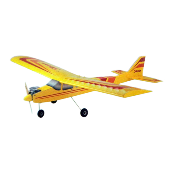
(this one will be for the opposite side APPLY TRIM of the stab). The main pictures show a Sierra covered in Mono- Kote yellow, red, and orange. Another attractive 4. Cut the pattern from the plan sheet, leaving a... -
Page 36: Install Receiver, Battery, Switch
HINT: You may carefully apply some thin CA decals are provided which you may use at your to the window lap joints with a toothpick to discretion, such as the "TOP FLITE" logo and the prevent them from peeling up. small "SIERRA" decals. -
Page 37: Balance Your Model
*NOTE: These control surface "throws" are FINAL CHECKS approximate and provide a good starting point for the first flights with your Sierra. You may wish NOTE: This section is VERY important and must 1. Make sure the control surfaces move in the... -
Page 38: Pre-Flight
transmitter and receiver batteries the night before RANGE CHECK YOUR RADIO RADIO SET-UP you go fly i ng, and at other times as recommended by the radio manufacturer. Wherever you do fly, you need to check the THREE CHANNEL AIRCRAFT operation of the radio before each flight. -
Page 39: Ama Safety Code
GENERAL the engine prior to flying. Run the engine set a little The Top Flite Sierra is a great flying airplane that rich for the first few flights in order to finish the break- flies smoothly and predictably. It is a primary trainer 1. -
Page 40: Take Off
After you have several flights on your Sierra, it's when gluing in the elevator joiner wire or aileron The Sierra will climb out at a 20 or 30 degree time to reward yourself with your first aerobatic torque rod; excessive flexing of aileron, caused angle under full throttle. -
Page 41: Landing
As you make the turn into the wind for yourfinal approach, pull the throttle back to idle. The Sierra has a lot of lift, so you will need a quite slow, reliable idle in order to achieve a nice, slow landing. - Page 42 TRANSPORTING CHECKLIST AFTER-FLIGHT MAINTENANCE BUILDING NOTES. Make sure radio batteries are all charged. We Kit Purchase Date Remove all excess fuel from the fuel tank, suggest checking the batteries with a ESV Meter as this fuel can become jelly-like and cause Where Purchased to make sure they are fully charged.
-
Page 43: Parts List
PLYWOOD DC FUSELAGE DIHEDRAL BRACES SIE4W14 PLYWOOD 1/16" TRAILING SIE4W04 BALSA 1/8" DC W-1A, W-1B DOUBLER EDGE PLATE SIE4P01 SIERRA FUSE PLAN SHEET SIE4W05 BALSA 1/16" DC WING SIE4P02 SIERRA WING PLAN SHEET CENTER SHEETS 1,4 SIE4W09 SUB-PACK. SHEAR WEBS SIE4P03... -
Page 44: 2-View Drawing
SIERRA TWO-VIEW DRAWING...
Need help?
Do you have a question about the Sierra and is the answer not in the manual?
Questions and answers