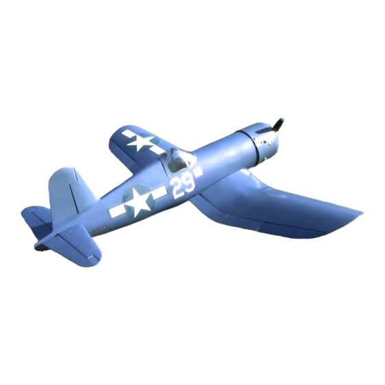
Top Flite F4U Corsair User Manual
Hide thumbs
Also See for F4U Corsair:
- Instruction book (44 pages) ,
- Instruction book (62 pages) ,
- Instruction manual (36 pages)
Table of Contents
Advertisement
Quick Links
WARRANTY
®
Top Flite
Model Manufacturing Co. guarantees this kit to be free from defects in both material and
workmanship at the date of purchase. This warranty does not cover any component parts damaged by use
or modification. In no case shall Top Flite's liability exceed the original cost of the purchased kit.
Further, Top Flite reserves the right to change or modify this warranty without notice.
In that Top Flite has no control over the final assembly or material used for final assembly, no liability shall be
assumed nor accepted for any damage resulting from the use by the user of the final user-assembled
product. By the act of using the user-assembled product, the user accepts all resulting liability.
If the buyer is not prepared to accept the liability associated with the use of this product, the buyer is
advised to return this kit immediately in new and unused condition to the place of purchase.
To make a warranty claim send the
defective part or item to Hobby
Services at this address:
Include a letter stating your name, return shipping address, as much contact information as possible (daytime
telephone number, fax number, e-mail address), a detailed description of the problem and a photocopy of the
purchase receipt. Upon receipt of the package the problem will be evaluated as quickly as possible.
READ THROUGH THIS MANUAL BEFORE STARTING CONSTRUCTION. IT CONTAINS IMPORTANT INSTRUCTIONS AND WARNINGS CONCERNING THE ASSEMBLY AND USE OF THIS MODEL.
®
Entire Contents © 2011 Hobbico,
Inc.
™
Hobby Services
3002 N. Apollo Dr. Suite 1
Champaign IL 61822 USA
Top Flite Models Champaign, IL
Ph: (217) 398-8970, Ext. 5
Fax: (217) 398-7721
airsupport@top-flite.com
SPECIFICATIONS
Wingspan:
86.5 in [2195mm]
Wing Area:
1376 sq in [88.8 dm
23– 25 lb
Weight:
[10430–11340 g]
Wing
39– 42 oz/sq ft
2
Loading:
[119–128 g/dm
]
Length:
70 in [1780mm]
Radio:
7 channel minimum,
10 channel is preferred
Engine:
3.0 – 4.0 cu in
[50– 55 cc] two-stroke
gasoline engine
2
]
TOPA0704 Mnl
Advertisement
Table of Contents

Related Manuals for Top Flite F4U Corsair


Summary of Contents for Top Flite F4U Corsair
- Page 1 Further, Top Flite reserves the right to change or modify this warranty without notice. 23– 25 lb In that Top Flite has no control over the final assembly or material used for final assembly, no liability shall be Weight: [10430–11340 g] assumed nor accepted for any damage resulting from the use by the user of the final user-assembled product.
-
Page 2: Table Of Contents
Corsair visit the Top Flite web site at are to avoid fl ying near full-scale aircraft and avoid Though the Top Flite Corsair is an ARF and may not fl ying near or over groups of people. have the same level of detail as an “all-out” scratch-built www.top-fl... -
Page 3: Important Safety Precautions
The radio equipment and number of channels required every fl ight. elevator. (FUTM4130) to fl y the Top Flite Giant Corsair ARF depends on the ❍ 1500 mAh NiCd receiver battery or equivalent 5. If you are not an experienced pilot or have not fl own capabilities of your transmitter and how the servos will (FUTM1285). -
Page 4: Engine Recommendations
For example #6 3/4" [19mm]. ❍ Pro 6-minute epoxy (GPMR6045) The Top Flite Giant Corsair ARF requires the use of This is a number six screw ❍ Silver solder w/fl ux (STAR2000) that is 3/4" [19mm] long. -
Page 5: Kit Inspection
30-minute To locate a hobby dealer, visit the Top Flite web by e-mail at or by telephone at (or 45-minute) epoxy, because you will need the site at www.top-fl ite.com. Select “Where to Buy” in productsupport@top-fl... -
Page 6: Preparations
PREPARATIONS The foam stand is also a great aid when installing the wing to the fuselage at the airfi eld. To assemble the ❏ 1. If you have not done so already, remove the major stand, slide the two plastic tubes into the foam cradles. parts of the kit from the box and inspect for damage. - Page 7 ❏ ❏ ❏ ❏ 2. Remove the aileron servo cover from the 5. There is a string that goes through the wing and bottom of the wing. Place your servo between the servo is attached to the root rib of the wing panel. If needed, mounting blocks located on the bottom of the cover.
- Page 8 HOW TO SOLDER 1. Use denatured alcohol or other solvent to thoroughly clean the pushrod. Roughen the end of the pushrod with coarse sandpaper where it is to be soldered. 2. Apply a few drops of soldering fl ux to the end of the pushrod, then use a soldering iron or a torch to heat it.
-
Page 9: Install The Main Landing Gear
Japanese A6M Zero, but even then work was underway to provide them with better aircraft. One of those better aircraft was the Vought “F4U Corsair”, a rugged, powerful, and somewhat unforgiving aircraft that featured a distinctive inverted gull wing. - Page 10 ❏ ❏ 4. On the top of the wing center section there is a hole located at the front of the wing where you will fi nd a string attached. Gently pull the string that the air line is attached to, pulling the air line out of the hole. Do not pull too hard causing the string to break! If the lines get caught on a rib while pulling the air line through the wing, pull the air line and string back out,...
- Page 11 ❏ ❏ ❏ ❏ ❏ ❏ 9. Using the pilot holes you drilled as your guide, 11. Position the nylon landing gear door mounts 13. Locate the door cover. Drill a 3/32" [2.4mm] drill a 7/64" [2.8mm] hole through each of the pilot holes on the back of the landing gear door, centering the hole in each corner of the cover.
-
Page 12: Final Wing Assembly
FINAL WING ASSEMBLY ❏ ❏ 1. Locate two nylon pins. Test fi t the pins into the holes in the leading edge of the wing. When you are satisfi ed with the fi t, apply epoxy to the ribbed end of the pins and into the holes in the wing. - Page 13 ❏ ❏ 4. Tape the leads to the wing to prevent them from dropping back into the wing. ❏ ❏ 5. Glue a nylon pin into the forward hole in the root rib of the wing center section. The pin should extend approximately 1/2"...
- Page 14 aligned properly the bolt will thread through smoothly. Leave the bolt in place for the next couple of steps. ❏ ❏ 7. On the top of the wing towards the trailing edge of the wing is a pre-drilled and tapped hole. Insert and ...
-
Page 15: Assemble The Fuselage
to align the fl ap on the outer wing panel with the fl ap INSTALL THE RUDDER & STAB / ELEVATOR tab extending from the fl ap in the wing center section. Once you are satisfi ed with the fi t of the wing and center section remove the outer wing panel. - Page 16 the bottom of the stabilizer. This can be a bit diffi cult. We found it was easiest to do this with a forceps by grabbing the head of the bolt and feeding it down into the holes. You can also use a magnetized ball wrench or by placing a small amount of clay into the head of the bolt and inserting the ball wrench into it.
-
Page 17: Install The Tail Wheel Asssembly
❏ pull wire, (2) crimp connectors, steering arm, (3) 1/8" 7. Prepare two 48" [3.2mm] wheel collars and (4) set screws.. [1220 mm] threaded pushrod wires by installing a 4-40 nut, 4-40 threaded clevis (20 turns) and silicone clevis keeper. ❏... - Page 18 ❏ ❏ 4. Use wire cutters to cut the supplied braided cable 7. Slide the wires into the plastic tubes in the back into two equal lengths. Slide a crimp connector over one of the fuselage. end of the cables, then guide the end of the cable back through the hole in the steering arm and back through the crimp connector.
-
Page 19: Installing The Retractable Tail Wheel
INSTALLING THE RETRACTABLE TAIL WHEEL ❏ ❏ 3. Use wire cutters to cut the supplied braided cable 6. Now pull on the long end of the cable to reduce into two equal lengths. Slide a crimp connector over the size of the fi rst loop. Slip the loop over one of the one end of the cables, then guide the end of the cable ball link balls on the steering arm. -
Page 20: Install The Tail Wheel Doors (Optional)
❏ no need for set screws in the wheel collars. They are 3. Remove the doors from the fuselage and remove simply wheel spacers). the hinges from the doors. Apply a drop or two of oil to the center of the hinge to prevent the glue from getting INSTALL THE TAIL WHEEL DOORS in the hinge. -
Page 21: Install The Tail Cone
❏ forward to the front of the fuselage 1" [25mm]. Make a 8. Make sure your doors open and close smoothly. mark with a fi ne point felt tip pen. Do this on both sides Add a drop of oil to the hinges if they bind. The spring of the fuselage. -
Page 22: Install The Elevator & Rudder Servos
INSTALL THE ELEVATOR AND RUDDER SERVOS Note: Just a reminder, whenever a screw is threaded into wood sheeting or wood blocks we recommend that you install the screw and then remove it. Apply a drop of thin CA glue into the hole to harden the threads. After the glue has hardened, re-install the screw. -
Page 23: Install The Air Control System
servo. From the servo horn with the shortest set of arms, cut away the arms leaving a single servo arm. Enlarge the outer hole in the servo arm with a 3/32" [2.4mm] drill bit. ❏ 9. This is how the servo installation should look. Make sure you have put all of the clevis retainers in place and applied thread locker to the nuts. - Page 24 ❏ mark on the wire where it passes under the hole in the L o c a t e t h e end of the servo arm. Make a 90 degree bend in the instrument panel and wire on the mark. Cut off the excess wire 3/8" [9.5mm] temporarily install it into above the bend.
-
Page 25: Install The Engine, Throttle Servo
on which side of the fuselage you would like the valve and the air control valve. Install the air lines from the to be located and then open up the hole with a hobby air control valve to the air couplers. If you are unfamiliar knife or rotary tool. - Page 26 to use three of these spacers. The other pattern may 2-56 nut. Do the same to the choke arm if you will be be used for other brands. Install your mounting bolts activating the choke with a servo. (Note: We will be for the stand-offs into the back side of the fi...
- Page 27 ❏ ❏ ❏ 7. Temporarily install the spacers and stand-offs onto 8. Thread a nylon ball link onto one end of a 2-56 9. Install the throttle servo into the servo tray using the fi rewall. Mount the engine to the stand-offs. 1"...
- Page 28 cut off the excess pushrod from the inner pushrod tube. Remove the clevis and wire from the servo arm. Cut the inner pushrod tube and then screw the threaded wire and clevis into the tube. Re-install the clevis into the outer hole in the servo arm. Steps 14-21 are only if you will be installing a choke servo.
-
Page 29: Install The Cowl
the threaded wire in the clevis, determine where to cut off the excess pushrod from the inner pushrod tube. Remove the clevis and wire from the servo arm. Cut the inner pushrod tube and then screw the threaded wire and clevis into the tube. Re-install the clevis into the outer hole in the servo arm. - Page 30 hole with a drill press. If you do not have access to a drill press, be sure you are careful to drill the hole as straight as possible. ❏ 6. Install a 6-32 1-1/2" [38mm] socket head cap screw and #6 fl at washer into the front of the hardwood block and thread a 6-32 blind nut onto the screw.
- Page 31 ❏ 11. Bolt the lower blocks to the cowl ring with two 6-32 1-1/2" [ 38 mm] socket head cap screws and #6 fl at washers. Slide the ring in place and put two more ❏ 13. Locate the eight plywood rings shown in the photo. bolts into the top two blocks.
- Page 32 ❏ Use CA accelerator to quickly harden the glue. After the 18. With a fi ne tip felt marker trace the outline of the glue has hardened remove the cowl from the fuselage. cylinder head onto the inside of the cowl. A note about the cowl mounting screws.
- Page 33 ❏ ❏ 23. Place the former back onto the backside of the 25. To add some additional details to the dummy dummy engine. Then, trace the shapes shown onto the engine, drill a 1/8" [3mm] hole into each of the rockers back of the dummy engine.
- Page 34 ❏ ❏ ❏ 27. Glue the former onto the back side of the dummy 29. Adjust the position of the dummy engine until it is 32. Apply RTV silicone glue to the dummy engine engine. centered properly in the cowl. The dummy engine should former.
-
Page 35: Install The Fuel Tank & Ignition Module
INSTALL THE FUEL TANK AND IGNITION MODULE ❏ 34. Temporarily mount the muffl er to the engine. We have recommended the J’tec Radiowave wrap-around Pitts muffl er (JTCG1035) for installation in the Corsair. This muffl er fi ts without making any modifi cations to the fuselage. - Page 36 ❏ The next few steps refer to the installation of the ignition 7. Trim the excess fuel line from the vent and fi ll lines. switch and charge jack. The installation will require that Re-install the engine onto the stand-offs. This is the last you glue the components to the fuselage.
- Page 37 ❏ 14. Glue the charge receptacle into the fuselage. We also used a couple of small wood screws. Because they are only screwed into balsa you will need to insert the screws and then remove them and apply a couple of drops of thin CA to harden the threads before re- inserting the screws.
-
Page 38: Install The Receiver, Battery & Complete The Radio Installation
❏ ❏ 15. Following the instructions that came with the 3. Install your radio switch and charge jack in the engine, fi nish the connections for the engine, ignition fuselage. Locate this switch as far away from the and the battery / switch harness. Be sure to secure the ignition switch and battery as is practical. -
Page 39: Install The Cockpit, Pilot & Canopy
❏ INSTALL THE COCKPIT, PILOT 3. A 1/5 scale pilot is correct for this model. We used a pilot from Vailly Aviation, www.vaillyaviation.com. If AND CANOPY you will be installing a pilot, glue it in place now. We have provided a cockpit interior that, on its own, gives a very realistic look to the interior of the aircraft. -
Page 40: Apply The Decals
❏ 2. Locate the two piece aluminum spinner. Install 4-CHANNEL RADIO SETUP (STANDARD MODE 2) the back plate onto the motor shaft using the mounting RIGHT AILERON bolts that came with the engine. Secure the spinner MOVES UP RUDDER with the 5 mm 50 mm socket head cap screw to the LEFT AILERON... -
Page 41: Balance The Model (C.g.)
(ready to fl y) and an empty fuel your fi rst fl ight will be successful. If you value your tank, place the model upside-down on a Top Flite CG model and wish to enjoy it for many fl ights, DO NOT Machine, ™... -
Page 42: Balance The Model Laterally
● Keep these items away from the prop: loose clothing, number on or inside your model. It is required at all We use a Top Flite Precision Magnetic Prop Balancer shirt sleeves, ties, scarfs, long hair or loose objects AMA R/C club fl ying sites and AMA sanctioned fl ying... -
Page 43: Ama Safety Code (Excerpts)
● Use a “chicken stick” or electric starter to start the ❏ RADIO CONTROL 2. Check the C.G. according to the measurements engine. Do not use your fi ngers to fl ip the propeller. provided in the manual. 1) I will have completed a successful radio equipment ●... -
Page 44: Flying
❏ things to remember with a tail dragger is to always be 18. Cycle your receiver battery pack (if necessary) CAUTION (THIS APPLIES TO ALL R/C AIRPLANES): ready to apply right rudder to counteract engine torque. and make sure it is fully charged. If, while fl... - Page 45 down as you turn onto the crosswind leg and deploy the If you are not accustomed to an airplane with fl aps This is not necessarily to improve your skills (though fl aps. When you deploy the fl aps expect it to balloon a you will discover that landings are slightly different.
- Page 46 This system has the identical footprint to the pneumatic gear so they are interchangeable with the pneumatic system. If you choose to use these in your Top Flite Giant Corsair simply install them using the procedure outlined in this manual, ignoring the instructions about the air lines, control valve, etc and use the instructions with the landing gear.
-
Page 47: Dle Mounting Pattern
DLE 55 Mounting Pattern Identification Tag This model belongs to: Name Address City, State, Zip Phone Number AMA Number...
Need help?
Do you have a question about the F4U Corsair and is the answer not in the manual?
Questions and answers