Top Flite P-51D Mustang Manual
Hide thumbs
Also See for P-51D Mustang:
- User manual (60 pages) ,
- User manual (58 pages) ,
- Instruction manual addendum (4 pages)
Table of Contents
Advertisement
™
WARRANTY.....
free from defects in both material and workmanship at the date of purchase. This
warranty does not cover any component parts damaged by use or modifi cation. In
no case shall Top Flite's liability exceed the original cost of the purchased kit.
Further, Top Flite reserves the right to change or modify this warranty without notice.
In that Top Flite has no control over the fi nal assembly or material used for fi nal
assembly, no liability shall be assumed nor accepted for any damage resulting from
the use by the user of the fi nal user-assembled product. By the act of using the user-
assembled product, the user accepts all resulting liability.
READ THROUGH THIS MANUAL BEFORE STARTING CONSTRUCTION. IT CONTAINS IMPORTANT INSTRUCTIONS AND WARNINGS CONCERNING THE ASSEMBLY AND USE OF THIS MODEL.
Top Flite Models Champaign, IL
Entire Contents © Copyright 2007
®
Top Flite
Models guarantees this kit to be
Telephone (217) 398-8970, Ext. 5
If the buyer is not prepared to accept the liability associated with the use of this
product, the buyer is advised to return this kit immediately in new and unused
condition to the place of purchase.
To make a warranty claim send the defective
part or item to Hobby Services at the address:
Include a letter stating your name, return shipping address, as much contact information
as possible (daytime telephone number, fax number, e-mail address), a detailed
description of the problem and a photocopy of the purchase receipt. Upon receipt of
the package the problem will be evaluated as quickly as possible.
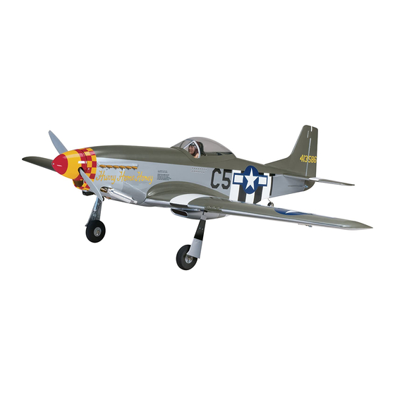
Wingspan: 64.5 in [1640mm]
Wing Area: 721 sq in [46.5 dm
2
]
Weight: 8.75 – 10 lb [3970 – 4540g]
Wing Loading: 28 – 32 oz/ft
2
[85 – 98g/dm
Length: 56 in [1420mm]
Radio: 6+ channel with 8 servos
Engine: .60 – .91 cu in [10 – 15cc] two-stroke,
.90 – 1.20 cu in [15 – 20cc] four-stroke
Hobby Services
3002 N. Apollo Dr., Suite 1
Champaign, IL 61822 USA
airsupport@top-fl ite.com
TOPZ0950 for TOPA0950 V1.0
2
]
Advertisement
Table of Contents

Related Manuals for Top Flite P-51D Mustang


Summary of Contents for Top Flite P-51D Mustang
- Page 1 Include a letter stating your name, return shipping address, as much contact information In that Top Flite has no control over the fi nal assembly or material used for fi nal as possible (daytime telephone number, fax number, e-mail address), a detailed assembly, no liability shall be assumed nor accepted for any damage resulting from description of the problem and a photocopy of the purchase receipt.
-
Page 2: Table Of Contents
Install the Retract Servo ..........13 For the latest technical updates or manual corrections Finish the Wing ............13 to the P-51 Mustang ARF visit the Top Flite web site 1. Your P-51 Mustang ARF should not be considered Optional Strut Cover Installation ........14 a toy, but rather a sophisticated, working model that at www.top-fl... -
Page 3: Decisions You Must Make
Though the Top Flite P-51 Mustang ARF may not have to operate the air valve. One standard torque servo the same level of detail as an “all-out” scratch-built such as an S3003 is required for the throttle. -
Page 4: Additional Items Required
Masking tape (TOPR8018) (SAE HCAR0520) ❏ ❏ If you would like photos of the full-size P-51D Mustang Denatured alcohol (for epoxy clean up) Hobbico 7-piece ball tip hex wrench ❏ for scale documentation, or if you would like to study... -
Page 5: Kit Inspection
3" = 76.2mm Telephone: (217) 398-8970 1/8" = 3.2mm 6" = 152.4mm Fax: (217) 398-7721 To order replacement parts for the Top Flite 5/32" = 4.0mm 12" = 304.8mm E-mail: airsupport@top-fl ite.com P-51 Mustang ARF, use the order numbers in the 3/16"... -
Page 7: Preparations
PREPARATIONS in the wing TE. Push the fl ap up against the wing so that the fl ap LE and the wing TE edge touch. If ❏ the two surfaces cannot touch, carefully deepen the 1. If you have not done so already, remove the hinge point pockets in the wing panel with a 3/16"... - Page 8 panel. Wipe away any excess epoxy from around the pockets using a paper towel dampened with alcohol. ❏ ❏ 6. Coat the other end of each hinge point up to LE of the fl ap. Slowly join the fl ap to the wing while wiping away any excess epoxy that squeezes out of the pockets.
-
Page 9: Mount The Servos
knife to slightly enlarge the slots. Push a pin (T-pins MOUNT THE SERVOS work well for this) through the middle of each hinge to keep them centered. Before completing this section, confi rm that the servos that you will be using will properly fi t between the servo mounting block locations on the aileron and fl... -
Page 10: Install The Aileron & Flap Pushrods
❏ ❏ 7. Mount the fl ap servo and hatch cover in the same way. The fl ap servo does not require a servo lead extension. ❏ 8. Repeat steps 1 to 7 for the left wing panel. Make note that the fl ap servo arm will be mounted on the root rib side of the left wing panel so that when the fl... -
Page 11: Join The Wing Panels
screw through each hole and back it out. Apply a the clevis and tighten the 2-56 nut against it. Slide JOIN THE WING PANELS couple drops of thin CA glue to each hole to harden the silicone clevis retainer to the end of the clevis to the wood. - Page 12 that the sides are fl ush with each other. Wipe away half of the wing joiner and slide it into one wing panel. any excess epoxy with denatured alcohol. Small Coat the root ribs of both wing panels as well as the clamps can be used to hold the pieces together while exposed ends of the joiner and anti-rotation pin.
-
Page 13: Install The Retract Servo
lock pushrod connectors and servo arm position. If the pushrod length interferes with the rotation of the servo, cut them shorter as necessary. When satisfi ed, secure the servo arm to the servo using the servo arm screw included with the servo. ❏... -
Page 14: Optional Strut Cover Installation
OPTIONAL STRUT COVER INSTALLATION struts using eight 2-56 x 1/2" [13mm] machine screws and eight 2-56 nuts. Painted strut covers are provided for added realism and can be installed at the modeler’s discretion. ASSEMBLE THE TAIL SECTION INSTALL THE HORIZONTAL STABILIZER, ELEVATORS, SERVOS &... - Page 15 the stab saddle in the fuselage with the control horn pointing down toward the clevis. Slide the horizontal stab into the saddle in front of the joiner rod. Temporarily (without glue) join the elevator halves to the stab with CA hinges. The ends of the joiner rod fi...
- Page 16 position of the stab, use a felt tip marker to mark the elevator hinge slots. Apply a light coating of epoxy to wire and the clevis are hot enough the solder will outline of the fuselage onto the top and bottom of it. the ends of the joiner rod and join the elevators to the fl...
-
Page 17: Install The Rudder, Tail Wheel & Linkages
INSTALL RUDDER, TAIL WHEEL and install the servo arm perpendicular to the servo case. Secure the servo arm with the servo arm screw. & LINKAGES Place the servo onto the servo tray in the fuselage in the position shown with the servo spline facing forward. -
Page 18: Install The Power System & Receiver
onto a 36" [914mm] pushrod 15 complete turns. the 90° bend into the second to outer hole in the Insert the pushrod into left pushrod exit slot in the servo arm and secure it with a nylon FasLink. Thread fuselage. Connect the clevis to a nylon control horn a 2-56 nut, metal clevis, and silicone clevis retainer and position the horn on the left side of the rudder onto the aft end of the pushrod. - Page 19 vent line, carb line, and fi ll line. If installing a fi ll line, mark on the engine mount with the lines on the fi rewall. puncture the top of the stopper above the sealed off Slide the mount halves against the sides of the engine fuel tube hole.
-
Page 20: Install The Receiver & Battery
threads in the four mounting holes. Attach the engine INSTALL THE RECEIVER & BATTERY to the mount using four 8-32 x 1" [25mm] SHCS, four #8 fl at washers, and four #8 lock washers. ❏ 1. Glue the fuel tank brace to the receiver tray in the direction shown. -
Page 21: Finish The Model
using four #2 x 3/8" [9.5mm] self-tapping screws and back of the fuselage. We used a small piece of fuel four #2 fl at washers. Be sure to harden the screw tubing glued to the side of the fuselage to hold the holes with thin CA. -
Page 22: Install The Cockpit & Canopy
thin CA into each hole to harden the wood. Position the INSTALL THE COCKPIT & CANOPY cowl onto the fuselage and shift it to one side in order to install the muffl er onto the header pipe. Install the cowl onto the fuselage using seven #2 x 3/8" [9.5mm] self-tapping screws and seven #2 fl... -
Page 23: Install The Propeller & Spinner
provided for use with a two-stroke engine, and a OPTIONAL PNEUMATIC RETRACTS spinner nut is also provided for use with the O.S. .91 four-stroke engine. Install the propeller and prop washer onto the crankshaft and tighten it down with the appropriate spinner nut. ❏... -
Page 24: Apply The Decals
APPLY THE DECALS control surface as indicated in the chart that follows. If your radio does not have dual rates, we recommend 4-CHANNEL RADIO SETUP ❏ setting the throws at the low rate setting. 1. Use scissors or a sharp hobby knife to cut the (STANDARD MODE 2) decals from the sheet. -
Page 25: Balance The Model (C.g.)
BALANCE THE MODEL (C.G.) screws, RTV silicone or epoxy to permanently hold the weight in place. More than any other factor, the C.G. (balance point) ❏ 4. IMPORTANT: If you found it necessary to add can have the greatest effect on how a model fl ies, any weight, recheck the C.G. -
Page 26: Balance Propellers
Make all engine adjustments from behind the We use a Top Flite Precision Magnetic Prop Balancer rotating propeller. (TOPQ5700) in the workshop and keep a Great Planes Fingertip Prop Balancer (GPMQ5000) in our The engine gets hot! Do not touch it during or right fl... -
Page 27: Ama Safety Code (Excerpts)
recommendations. Do not use hands, fi ngers or any AMA SAFETY CODE (EXCERPTS) 3) At all fl ying sites a straight or curved line(s) must other body part to try to stop the engine. To stop a be established in front of which all fl ying takes place gasoline powered engine, an on/off switch should be with the other side for spectators. -
Page 28: Check List
❏ CHECK LIST FLYING 12. Secure connections between servo wires and Y-connectors or servo extensions, and the connection between your battery pack and the The P-51 Mustang ARF is a great-fl ying model that During the last few moments of preparation your mind on/off switch with vinyl tape, heat shrink tubing fl... -
Page 29: Takeoff
TAKEOFF at slower speeds. Also, at slower speeds, lower the will be required to maintain heading), remember to fl aps and note any trim change. Add power to see how throttle back at the top, and make certain you are she climbs as well. - Page 30 B-25J Mitchell This B-25J Mitchell has plenty of room for scaling out...and Top Flite makes the most of it, while keeping assembly time to just 50 hours. The functional fi berglass gear doors can be locked fully deployed to accommodate the supplied fi xed gear – or add Robart retracts (available separately) for maximum realism. Fly the B-25J on a pair of .40s or install two .70 4-strokes for more power.
- Page 31 FLIGHT LOG Started Construction Finished Construction First Flight Notes...
Need help?
Do you have a question about the P-51D Mustang and is the answer not in the manual?
Questions and answers