Table of Contents
Advertisement
Quick Links
WARRANTY.....
warranty does not cover any component parts damaged by use or modification. In no case shall Top Flite's liability exceed the original cost of the purchased
kit. Further, Top Flite reserves the right to change or modify this warranty without notice. In that Top Flite has no control over the final assembly or material
used for final assembly, no liability shall be assumed nor accepted for any damage resulting from the use by the user of the final user-assembled product.
By the act of using the user-assembled product the user accepts all resulting liability. If the buyer is not prepared to accept the liability associated with the
use of this product, the buyer is advised to immediately return this kit in new and unused condition to the place of purchase.
Top Flite Models P.O. Box 788 Urbana, Il 61803
READ THROUGH THIS INSTRUCTION BOOK FIRST. IT CONTAINS IMPORTANT INSTRUCTIONS AND WARNINGS CONCERNING THE ASSEMBLY AND USE OF THIS MODEL.
Entire Contents © Copyright 2000
Top Flite Models guarantees this kit to be free of defects in both material and workmanship at the date of purchase. This
Technical Assistance Call (217)398-8970 www.top-flite.com
™
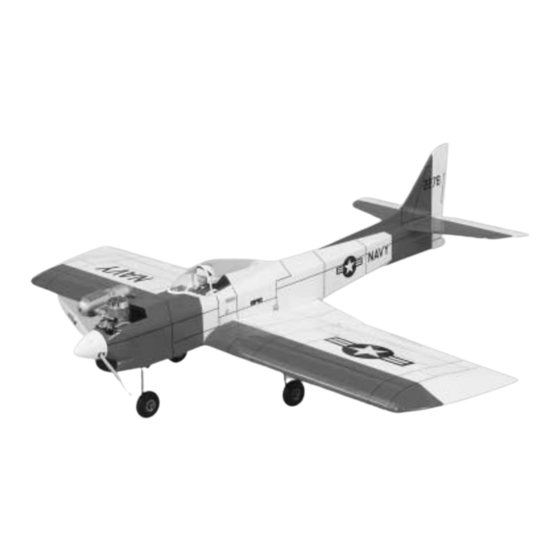
Wingspan:
53-1/4" [1353 mm]
Wing Area:
660 sq. in.
[42.6 sq.dm.]
Weight:
6 - 6-1/2 lbs
[2721 - 2948 grams]
Wing Loading:
21 - 23 oz./sq. ft.
[64 - 70 g/sq.dm.]
Fuselage Length:
49-5/8" [1261 mm]
Engine Required:
2-Stroke .40 - .61 or
4-Stroke .52 - .70
CTD6P03
™
V1.1
Advertisement
Table of Contents

Related Manuals for Top Flite Contender


Summary of Contents for Top Flite Contender
- Page 1 In no case shall Top Flite’s liability exceed the original cost of the purchased kit. Further, Top Flite reserves the right to change or modify this warranty without notice. In that Top Flite has no control over the final assembly or material used for final assembly, no liability shall be assumed nor accepted for any damage resulting from the use by the user of the final user-assembled product.
-
Page 2: Table Of Contents
INSTALL THE SERVOS AND PUSHRODS..26 such as loops, stall turns, rolls, etc. Its structure is Your Top Flite Contender is not a toy, but a Make the pushrods........26 designed to withstand such stresses. If you intend to sophisticated working model that functions very Install the servos in the fuselage ....26... -
Page 3: Introduction
Do not alter or modify the model, as .40 to .61 cu. in. [7.5cc to 10cc] 2-stroke you are eager to build and fly your Contender just as doing so may result in an unsafe or unflyable model. .52 to .70 cu. in. [8.5cc to 11.5cc] 4-stroke we were eager to build and fly our prototypes. -
Page 4: Flight Characteristics
Top Flite Trim Seal Tool (TOPR2200) These are additional items you will need to complete -and- your Contender that are not included with your kit. 4 oz. [120g] Thin CA (GPMR6004) Top Flite Sealing Iron (TOPR2100) Order numbers are in parentheses (GPMQ4130). -
Page 5: Important Building Notes
When you see the term test fit in the instructions, it TYPES OF WOOD Contender we used two 5-1/2" [140mm] Bar Sanders means that you should first position the part on the and two 11" [280mm] Bar Sanders equipped with 80- assembly without using any glue, then slightly grit and 150-grit Adhesive-backed Sandpaper. -
Page 6: Die-Cut Patterns
DIE-CUT PATTERNS... -
Page 7: Get Ready To Build
GET READY TO BUILD 7. Use leftover pieces of the 1/4" x 3/8" x 30" [6.4 x 9.5 x 762mm] balsa sticks to make the 1/4" [6.4mm] balsa gussets. Cut them as shown on the 1. Unroll the plan sheets. Roll them inside out so plan and glue them in place. -
Page 8: Build The Rudder
Build the rudder 1.Work on a flat surface over the plan. Pin the rudder plan to the building board and cover the plan with Plan Protector. The plan may be cut apart if space is a problem. 10. Insert a T-pin through the center of the 2. -
Page 9: Install The Hinges
7. Remove the assembly from the plan. If you choose not to purchase a Slot Machine you can make the slots following these instructions. 8. Final sand the fin assembly. Shape the LE of the fin and the top of the dorsal fin to the shape shown on the plan. -
Page 10: Install The Control Horns
8. Cut a slot in the leading edge of both elevator halves to accommodate the joiner wire. This can be done easily with the Great Planes “Groove 2. Check for correct alignment. Drill two 3/32" Tube”™ as shown in the photograph. Hint: If you do [2.4mm] holes for the control horn mounting bolts 5. -
Page 11: Build The Wing
BUILD THE WING sure when you place the ribs that all of the ribs have the jig tab in contact with the building board. Place the remaining wing spar in position on the bottom of Build the bottom of the wing the wing in the notches on the ribs W-1, W-2 and W- 1. - Page 12 21. If you plan to install the optional flap, (and if you’re not, how come? It really is a lot of fun and adds another dimension to flying the Contender!) cut two additional 4-1/4" [108.4mm] servo rails from the 13. Locate the two die-cut balsa 3/32" [2.4mm] half remainder of the 1/4"...
- Page 13 26. See the Hot Tip that follows, then glue one of the 3/32" x 3" x 24" [2.4 x 76 x 610mm] balsa sheets to one of the 3/32" x 3/4" x 24" [2.4 x 19.1 x 610mm] balsa sheets to make one 3-3/4" [95mm] sheet. Make four sheets for the top and bottom LE wing sheeting.
-
Page 14: Build The Top Of The Wing
the sheeting down making sure it contacts the surface Build the top of the wing of each rib and the sub LE. Hold it in place until the glue has cured. 1. Remove the wing from the building board. Turn the wing over and place it over the plan and we’ll 28. - Page 15 13. Use a razor plane to shape the wing LE to the shape shown on the plan. Sand the wing LE to its final shape. 9. Glue one of the 1-1/2" x 2-1/8" [38 x 54.2mm] 4. Fully seat the top wing spar in the rib notches and balsa shear webs in place between the W-3 ribs for glue in place.
-
Page 16: Build The Ailerons
1. You must build the flap regardless of whether you are going to have it operational or fixed. The In the 1970’s the Contender was one of the construction steps are the same. “must have” models. It was extremely popular as a sport plane and was particularly well suited as a fun fly contest airplane. -
Page 17: Build The Wing Tips
TE of the aileron. Before we can continue, you’ll need to decide which wing tip shape you wish to use on your Contender. The standard tip is the original “nostalgia” tip shape C C o o n n t t e e n n d d e e r r F F u u n n F F a a c c t t and the model performs quite nicely with this tip. -
Page 18: Optional Wing Tips
Install the aileron and flap hinges 1. If you have been following the instructions you should already have the hinge slots located in the leading edge of the ailerons and flap. Hold the aileron in place on the wing and mark the location where the hinge slots need to be cut into the wing TE. - Page 19 5. Test fit formers F-2A, F-3A, F-4A and F-5A into the slots in the upper fuse deck with the lettering 8. Glue the left fuselage side in place on the upper 2. Locate the two die-cut 1/8" [3.2mm] balsa upper facing forward.
- Page 20 HobbyLite ™ . Allow the filler to completely harden. 14. Edge glue two pieces of 3/32" [2.4mm] balsa Trim the protruding pushrod guide tube to within 1/8" and cut it to fit the area where the flap rests on the from the fuse side.
- Page 21 29. Position the die-cut 1/8" [3.2mm] ply fuel tank hatch on the bottom of the fuselage. Drill a 1/16" [1.6mm] hole in each corner of the hatch making 22. Use 30-minute epoxy to glue the firewall in 25. Position the engine on the engine mount at sure that the holes go into the firewall and F-2.
- Page 22 on the plan as a pattern. Place the forward dorsal fin support to match the dorsal fin, as shown in the in position behind F-3C. Place the fin assembly in above photo. Sand the fin supports to the shape as place on top of the fuselage.
-
Page 23: Make The Cowl
Make the cowl 1. Screw the engine to the engine mount before you perform the next few steps. 5. From the 1/2" x 3" x 15" [12.7 x 76 x 381mm] balsa block cut two balsa cowl sides. Fit them 7. -
Page 24: Mount The Wing
2. Position the wing in the saddle. If any minor 8. Use a 1/4-20 tap to tap the threads in the maple sanding needs to be done to get a good fit between wing blocks. After you have the holes tapped, put a the fuselage and the wing do it now. -
Page 25: Mount The Stab
Mount the stab 5. Before the glue cures make sure that you align the stab to be parallel with the wing as shown in the sketch. 4. Remove the fuel tank hatch, then place the steering arm assembly between the nose gear mounts on the firewall. -
Page 26: Install The Servos And Pushrods
INSTALL THE SERVOS AND 8. Enlarge one outside hole in the elevator and PUSHRODS rudder servo arms with a 5/64" bit. Make a 90 degree bend in each of the pushrods at the point that you marked. Cut off the excess wire, leaving about 3/8" Make the pushrods after the bend. -
Page 27: Install The Aileron Servos
With the .46 engine it balanced close to the C.G. We recommend that you Top Flite LustreKote is a high quality, fuel proof paint check the balance of your airplane before locating that perfectly matches Top Flite MonoKote. The the battery and receiver. -
Page 28: Finishing
3. Forward fuse bottom We’ve installed the radio system. All the hinge slots Contender. The Top Flite MonoKote Trim Seal Tool 4. One fuse side, then the other (with the two are cut and the control surfaces are all temporarily is highly recommended for this model. -
Page 29: Join The Control Surfaces
3/8" [10mm] forward or back The first method is to use a Top Flite Panel Line Pen to change the flying characteristics. If you move the (TOPQ2510) with a flexible straightedge. Apply a few 5. -
Page 30: Final Hookups And Checks
The balance point and control surface throws listed sanctioned flying events. in this manual are the ones at which the Contender 1. Take the servo arms off the servos, turn on the flies best. Set up your aircraft to those specifications. -
Page 31: Balance The Propeller
Engine We use a Top Flite Precision Magnetic Prop exhaust gives off a great deal of deadly carbon To stop the engine, close the carburetor barrel (rotor) Balancer™... -
Page 32: Flying
The flight characteristics of this plane are very good in the proximity of full scale aircraft. We hope you enjoyed building the Contender. Top at all ranges of the flight envelope. Slow speed flight Flite has a number of other outstanding .60 size is stable and shows no sign of tip stalling.
Need help?
Do you have a question about the Contender and is the answer not in the manual?
Questions and answers