Table of Contents
Advertisement
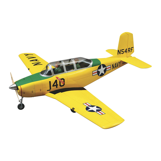
80 in [2032 mm]
Wingspan:
1025 sq in [66.1 sq dm]
Wing Area:
10 to 14 lb [4536 – 6350 g]
Weight:
22.5 to 31.5 oz/sq ft
Wing Loading:
[68.7 – 96.1 g/sq dm]
Fuselage Length:
62.8 in [1595 mm]
WARRANTY.....
not cover any component parts damaged by use or modification. In no case shall Top Flite's liability exceed the original cost of the purchased kit. Further, Top Flite reserves
the right to change or modify this warranty without notice. In that Top Flite has no control over the final assembly or material used for final assembly, no liability shall be assumed
nor accepted for any damage resulting from the use by the user of the final user-assembled product. By the act of using the user-assembled product the user accepts all resulting
liability. If the buyer is not prepared to accept the liability associated with the use of this product, the buyer is advised to immediately return this kit in new and unused
condition to the place of purchase.
Top Flite Models P.O. Box 788 Urbana, Il 61803
READ THROUGH THIS INSTRUCTION BOOK FIRST. IT CONTAINS IMPORTANT INSTRUCTIONS AND WARNINGS CONCERNING THE ASSEMBLY AND USE OF THIS MODEL.
Entire Contents © Copyright 2002
Top Flite Models guarantees this kit to be free of defects in both material and workmanship at the date of purchase. This warranty does
Technical Assistance Call (217)398-8970 productsupport@top-flite.com
™
T349P03 for TOPA0160 V1.0
Advertisement
Table of Contents

Related Manuals for Top Flite T-34B MENTOR


Summary of Contents for Top Flite T-34B MENTOR
- Page 1 In no case shall Top Flite‘s liability exceed the original cost of the purchased kit. Further, Top Flite reserves the right to change or modify this warranty without notice. In that Top Flite has no control over the final assembly or material used for final assembly, no liability shall be assumed nor accepted for any damage resulting from the use by the user of the final user-assembled product.
-
Page 2: Table Of Contents
MOUNT THE NOSE LANDING GEAR ....46 MINDED MODELERS........5 Fixed gear .............46 DOCUMENTATION..........5 Your Beechcraft T-34B Mentor is not a toy, but a Retractable nose gear ........47 NOTES FROM THE DESIGNER ......5 FINISH CONSTRUCTION ........49 sophisticated working model that functions very DIE-CUT PATTERNS........6 &... -
Page 3: Introduction
But since this is a Top Flite Gold the ground and in the air. NOTE: We, as the kit manufacturer, provide you Edition kit, it isn’t more difficult to build than those... -
Page 4: Decisions You Must Make
.75 [12.3 cc] engines and For Retractable Landing Gear you will need will fly the T-34B Mentor well. If you use a .60 [9.8 cc] these items (not included): 2-stroke, a ball bearing, Schnuerle-ported engine is ❏... -
Page 5: Scale Cockpit Interior
The trim scheme of the T-34B Mentor on the kit box Landing Gear: If you are installing fixed gear you will Scale cockpit interior is from a T-34B Mentor owned by Rudy Frasca. If you note that the strut extends out from the center of the are going to compete in scale competition, use the grooved rail instead of the end. -
Page 6: Die-Cut Patterns
DIE-CUT PATTERNS IMPORTANT Do not remove the wing ribs or other wing parts from the die-cut sheets until instructed to do so. - 6 -... -
Page 7: Die-Cut Patterns
DIE-CUT PATTERNS - 7 -... -
Page 8: Other Items Required
CA and Epoxy. These are additional items you will need to complete 9/64” or #29, 3/16”, 11/64” or #10, 1/4”, 13/64” your T-34B Mentor that are not included with your kit. or #7 Glue/Filler Order numbers are in parentheses (GPMQ4130). -
Page 9: Important Building Notes
that step, i.e. the top main spar is always the top IMPORTANT BUILDING NOTES GET READY TO BUILD main spar even if the wing is upside-down when you are working on it. Similarly, move the former There are two types of screws used in this kit: up means move the former toward the top of the 1. -
Page 10: Build The Tail Surfaces
BUILD THE TAIL SURFACES MAKE THE SKINS FOR THE TAIL SURFACES ❏ 1. See the Hot Tip that follows and use six 1/16” x B. Tightly tape the sheets together with masking 3” x 30” [1.6 x 76 x 762mm] balsa sheets to make two tape placed about every 4”... -
Page 11: Build The Stab And Elevators
Follow this sequence: (2) planks – stab and rudder. (2) planks – stab and elevator. (2) planks – vertical fin and elevator. Beech Fact: In 1946 Walter H. Beech announced his all new, revolutionary, single engine entry in the postwar market. He named it the Bonanza, descriptive of an extra value offered in the way of economy, performance and pleasure to the owner. - Page 12 ❏ Use this photo for the next three steps. 15. Sand the top of the leading edges, stab and elevator spars, and the TE brace so they match the contour of the ribs. Do not change the shape of the airfoil by sanding too much.
- Page 13 ❏ ❏ 19. After the glue has thoroughly dried, remove all 26. Trim the elevator torque rod blocks and any the T-pins you can reach. Carefully lift the stab (with protruding hinge blocks so they are even with the the elevators) from your building board. Trim the jig bottoms of the ribs.
- Page 14 ❏ 32. Glue a die-cut 1/8” [3.2mm] balsa stab TE (S10) to the TE of both stab halves. Glue a die-cut 1/8” [3.2mm] balsa elevator LE (also S10) to the LE of both elevators. ❏ 33. Sand the stab TE’s and the elevator LE’s so they are even with the ends of the stab and HOW TO MAKE THE HINGE SLOTS elevators.
- Page 15 ❏ ❏ 47. Shape the leading edge of the elevator to a “V” as shown on the plan. Use the centerline on the leading edge as a guide. Make sure that the angle of the “V” will allow the throws indicated in the back of the manual.
-
Page 16: Build The Fin And Rudder
❏ 6. Sand the fronts of the ribs to match the aft sweep of the leading edge. Cut a shaped 5/16” x 15” [8 x 381mm] balsa stab/fin leading edge to a length of 11” [280mm]. Glue it to the front of the ribs so the top edge of the LE is even with the top of the ribs. - Page 17 ❏ ❏ ❏ 10. After the glue has thoroughly dried, remove all 17. Glue the die-cut 1/8” [3.2mm] balsa fin gusset 28. Draw a centerline on the top and bottom of the the T-pins you can reach. Carefully lift the fin (with to the hinge block and rib R6.
-
Page 18: Build The Wing
❏ What a nice piece of workmanship! Put the stab and 3. After the glue dries, remove the masking tape fin in a safe place, clean off your workbench, vacuum and mark the best side of each skin as the top. Sand the floor, then read the following T34 Fact. -
Page 19: Build The Outer Wing Panels
Perform steps F7 through F10 only if you are installing fixed landing gear. ❏ 11. Use a straightedge and a ballpoint pen to mark a vertical line 1/16” [1.6mm] from the front and back R5. Drill 5/32” [4mm] holes and cut slots at the ❏... - Page 20 through W9. If the spar fits too tightly use a single edge razor blade or a flat Perma-Grit sander to bevel the notches in the ribs and the spar at the same angle that they cross. Reinstall the aft inner spar. ❏...
-
Page 21: Sheet The Top Of The Wing Panels
Use this photo and the sketch for the next few Beech Fact: In 1952 the USAF ordered the YT-34 steps. This photo shows a few weights on top of the into production under the designation T-34A wing, but in actuality we used enough weights to fully Mentor. -
Page 22: Finish The Outer Wing Panels
❏ ❏ ❏ ❏ 5. Remove the T-pins from the bottom spar. The 10. Clean the glue blobs and wood chips off weights on the aft sheeting will hold your wing flat. your workbench so they won’t leave dents in your beautiful wing sheeting. - Page 23 accommodate the bottom skin. While you sand, apply ❏ ❏ R8. From a 1/4” x 3/8” x 24” [6.4 x 9.6 x pressure only to the sheeting and use the ribs to set 610mm] basswood stick, cut a piece that is 1-1/2” your sander at the correct angle.
- Page 24 ❏ ❏ F15. Cut the 1/4” x 1/2” x 9” [6.4 x 12.7 x 229mm] plywood flap servo hatch forward rail to a length of 3-1/16” [77.8mm]. Glue it into the notches of ribs W6 and W7. ❏ ❏ 19. Cut three 1-1/2” [38mm] long flap hinge blocks from the shaped 5/8”...
-
Page 25: Build The Center Section
❏ ❏ ❏ 23. Mark the locations of the aileron hinge slots 4. Glue two sets of die-cut 1/8” [3.2mm] plywood on the outer wing TE and the aileron LE, so you will wing bolt plates together to make two 1/4” know where to cut the hinge slots after the wing and [6.4mm] plates. -
Page 26: Sheet The Top Center Section
❏ Now for the fun part. . . SHEET THE TOP CENTER SECTION 5. Trim the aft skin so the front edge joins the forward skin and the aft edge extends past the ends ❏ ❏ 10. Fit the ribs onto the die-cut 1/8” [3.2mm] 1. -
Page 27: Prepare The Wing Bottom For Sheeting
PREPARE THE BOTTOM OF THE WING plywood dihedral braces W22 in the outer wing panel. If necessary chamfer the corners of the FOR SHEETING braces to accommodate small glue fillets in the wing. ❏ Note: Make certain you fit the braces right side up 1. -
Page 28: Sheet The Bottom Of The Wing Panels
❏ (not a felt-tip pen) to trace the outline of the landing front and rear of each cradle and tack glue them to the 16. Separate the wing panels and remove the gear onto the rails so you know where not to apply top wing sheeting in their proper locations. -
Page 29: Cut Out The Wheel Wells
❏ ❏ 8. Use the remainder of the 3/32” x 6” x 30” [2.4 x ❏ ❏ CUT OUT THE WHEEL WELLS R4. Brush another coat of fuelproof paint 152.4 x 762mm] balsa sheet you used for the forward inside the wheel wells while they are still easy to inner top skin to make a forward inner bottom skin. -
Page 30: Build The Flaps
BUILD THE FLAPS Skip this section if you are not building flaps. ❏ ❏ 1. Use a fine razor saw to cut only the ends of the flap from the wing along the holes you poked in the top sheeting. ❏... - Page 31 ❏ ❏ 14. Use the flap hinge drill guide to drill holes in the flap the same way you did for the wing. ❏ ❏ 11. Assemble the die-cut 1/8” [3.2mm] plywood flap hinge drill guides by gluing the pieces together as shown.
-
Page 32: Build The Ailerons
BUILD THE AILERONS ❏ ❏ 1. If you have built flaps, remove them from the right wing panel. Use a razor saw to separate the aileron from the wing by cutting between the LE of the aileron and the TE of the wing. Refer to the plan to find the location of this gap and poke a pin through the sheeting to verify you have found the gap. -
Page 33: Join The Wing Panels
❏ ❏ MAKE THE FLAP & AILERON PUSHRODS 5. Use 30-minute epoxy to glue the servo mount blocks, with the servo attached, to the servo hatch covers as shown on the plan. Roughen the hatches with sandpaper where the blocks will be glued so the glue will adhere better. -
Page 34: Build The Fuselage
❏ and a solder clevis. We recommend silver solder for 1. Position the bottom view of the fuselage plan the solder clevis (see the hot tip on soldering below). over your flat building board. Cover it with Plan Drill 1/16” [1.6mm] holes in the aileron horn mounting Protector or waxed paper. -
Page 35: Build The Bottom Of The Fuselage
❏ with thin CA. Trim the ends so they extend past former 6. If you plan to install the Top Flite Beechcraft F11 by approximately 1/8” [3.2mm]. You can see the T34B Scale Cockpit Kit (TOPQ8413), drill holes and splice in the following photo. -
Page 36: Mount The Servos
❏ ❏ 9. Locate two of the 24” [609.6mm] pushrod tubes. 12. Glue the 3/16” x 3/16” [4.8mm] side stringers Sand the outside of the tubes so glue will stick. Slide and pushrod guide tubes to the formers. them through the holes in formers F6 through F10 so ❏... -
Page 37: Sheet The Fuselage Sides
❏ ❏ ❏ SHEET THE FUSELAGE SIDES 2. Glue the other forward fuse doubler to the left 4. Test fit the side sheet and make any further side of the fuselage. Use 3/16” x 3/16” [4.8 x 4.8mm] adjustments necessary for a good fit. ❏... -
Page 38: Mount The Stab And Fin
❏ ❏ drill straight. Hint: A 6” [152mm] piece of 1/8” 8. Return to step 1 and glue another side sheet to 2. Securely glue the die-cut 1/8” [3.2mm] plywood [3.2mm] brass tube sharpened at one end cuts a the left fuse side the same way. stab saddles to the top of the main fuse side clean hole. -
Page 39: Center The Stab
❏ bushings from the white inner pushrod tube, then 2. Insert a T-pin in the center of the top of slide the bushings evenly spaced onto the wire. the firewall. Make sure the bushings at the ends of the wire will not protrude from the guide tube or the control could become stuck during flight. -
Page 40: Align The Stab Horizontally
ALIGN THE STAB HORIZONTALLY MOUNT THE FIN the LE of the fin. Insert the stick into the fin and check the fit of the stick and fin on the fuselage. The ❏ stick should extend to the hole for the receiver 1. -
Page 41: Build The Turtle Deck
Recheck that the fin is vertical in relation to the stab BUILD THE TURTLE DECK and that the TE of the fin is perpendicular to the main fuselage stringer. Also check that the TE of the ❏ fin is against the rudder torque rod and that the rod 1. - Page 42 ❏ ❏ ❏ ❏ 6. Use a ballpoint pen to mark the bottom of the 10. Trim another 1/16” x 3” x 24” [1.6 x 76.2 x ❏ stab onto the sheet. Remove the sheet and cut along 610mm] balsa sheet to fit between the bottom turtle 13.
-
Page 43: Build The Dorsal Fin
BUILD THE DORSAL FIN plan. Test fit and glue one of the sheets to the turtle elevators neutral, use a felt-tip pen to mark the deck and dorsal fin base. Wet the sheet and glue it to pushrods exactly 1-1/4” [31.8mm] from the holes in ❏... -
Page 44: Fit The Tail Cone
FIT THE TAIL CONE SHEET THE FUSELAGE BOTTOM ❏ 1. If you are going to hook up working lights, now is a convenient time to route the wire for the light in the tail. Route the wire through the formers. Glue the wire to the formers with rubber cement or a drop of CA so they don’t rattle around. -
Page 45: Mount The Engine
❏ MOUNT THE ENGINE 4. Glue the F1T/F1DT assembly to the top of the firewall. Use a straightedge to make sure they align. ❏ 5. Glue the die-cut 1/8” x 4” x 4” [3.2 x 101.6 x 101.6mm] plywood firewall doubler to the back of the firewall, centered on the engine mount punch marks, 1/8”... -
Page 46: Mount The Nose Landing Gear
gear braces. Cut the braces off at the line. Glue the two die-cut 1/8” [3.2mm] plywood nose gear plates together. Make sure the punch marks face out. ❏ 11. Mark the engine mounting bolt holes on the ❏ mount. Hint: Mark the holes with a wire rod F5. -
Page 47: Retractable Nose Gear
Note: While there are other retractable nose gear Mount the heavy-duty Screw-Lock connector to the units that may work in the Top Flite Gold Edition steering arm with the one-way star washer. Mount Beechcraft T-34B, the Robart 631 is shown in this the 3/16”... - Page 48 ❏ R11. Test fit the servo tray (with the servo) in the die-cut 1/8” [3.2mm] plywood servo tray mounts and fit the assembly in the servo rails. Position the mounts and the tray so the output shaft of the servo is centered between the 1/8” [3.2mm] holes in former F2.
-
Page 49: Finish Construction
FINISH CONSTRUCTION HOOK UP THE THROTTLE ❏ 1. Mount your engine mount and engine to the firewall. Mount your muffler to make sure your throttle pushrod will not interfere. ❏ R2. Install a 0-80 threaded ball link ball (not included) onto the arm on both sides of the nose wheel strut with a 0-80 nut. -
Page 50: Mount The Wing To The Fuse
MOUNT THE WING TO THE FUSE round such as a pen or a piece of brass tube. This will allow you to plug the wing into the fuselage Remember the wing? Go get it so you can mount it without too much resistance. to the fuse. - Page 51 drill the holes for the fuel lines. Drill the holes with a 1/4” [6.4mm] drill (15/64” [6mm] drill for a better fit). Coat the inside of the fuselage between the firewall and former F2, including the back of the firewall, with fuel proof paint, epoxy or finishing resin.
-
Page 52: Sheet The Forward Bottom
❏ ❏ 11. Use a short piece of 3/32” [2.4mm] balsa sheet and glue it in place on the top of the fuselage from the firewall to F2. The sheet should be trimmed at the center of the center stringer. Note that we traced the shape of the canopy onto the sheeting. -
Page 53: Fit The Canopy
If you are installing the optional cockpit kit (TOPQ8413) in your T-34B, you can skip the next step and follow the instructions supplied with the cockpit kit. ❏ 4. Cut the front canopy out on the cut lines and fit the canopy into place on the fuselage. -
Page 54: Sheet The Wing Center Section Bottom
If you are installing the optional cockpit kit SHEET THE BOTTOM OF THE WING (TOPQ8413) in your T-34B, you can skip the CENTER SECTION following steps and follow the instructions supplied ❏ with the cockpit kit. 1. Install your servo extension cords, “Y” connectors and air lines if you are installing retracts. -
Page 55: Make The Belly Pan
MAKE THE BELLY PAN fuselage. Feather the edges where the belly pan BUILD THE COWL meets the wing sheeting with lightweight hobby filler. ❏ After the filler dries, remove the wing and sand the 1. Bolt the wing to the fuselage. Place the die-cut belly pan to blend with the wing. - Page 56 ❏ 3. Tape the cowl together with masking tape. Test fit the cowl to the fuse. Glue the seams with thin CA. ❏ ❏ 6. Test fit eight 1/2” x 1/2” x 5/8” [12.7 x 12.7 x 10. If you have fixed landing gear, cut a slot in the 15.9mm] maple cowl mount blocks in the notches bottom of the cowl to clear the landing gear wire.
-
Page 57: Finishing
❏ and finish with 400-grit sandpaper. When you’re 16. Fill the seams in the cowl with Bondo filler. done your cowl should look something like the one in There are other fillers that you can use, but we have the photo–just enough Bondo left to fill in the low found that Bondo works the best. -
Page 58: Cockpit Details
❏ 6. Turtle deck (may be done in one or two There are many scale details you can add to your 3. Use a Top Flite Hot Sock to minimize dents in the pieces) T-34B that will really bring it to life. -
Page 59: Painting
JOIN THE CONTROL SURFACES MAKE THE PANEL LINES Use a Top Flite Panel Line Pen (TOPQ2510) to draw the panel lines and hatch outlines or use a Top Flite ❏ Smart Stripe™ (TOPR2420) to cut narrow strips of 5. Join the elevators to the stab with the hinges. If DRILL A 3/32"... -
Page 60: Apply The Decals
cleaners will remove the ink lines so test your GET YOUR MODEL READY TO FLY cleaner before you spray it on your model. You can remove mistakes with alcohol.You’ll need to touch up BALANCE YOUR MODEL some of the lines from time to time because they fade with lots of handling and fuel spillage. -
Page 61: Balance The Airplane Laterally
❏ 4. Cut the two 1/8” x 1” [3.2 x 25.4mm] dowels to Warning: Some modelers who built the Top Flite a length of 3/4” [19.1mm]. Glue the dowels into the Bonanza reported that the model was very pitch holes you drilled in the bottom of former F6. -
Page 62: Control Surface Throws
❏ 11. Make sure the control surfaces move in the CONTROL SURFACE THROWS: proper direction as illustrated in the following sketches. We recommend the following control surface throws: Note: Throws are measured at the widest part of the control surface. High Rate Low Rate ELEVATOR:... -
Page 63: Preflight
If you are not thoroughly familiar with the operation Use safety glasses when you operate model engines. The Top Flite Beechcraft T-34B is a great flying sport of R/C models, ask an experienced modeler to scale airplane that flies smoothly and predictably, yet inspect your radio installation and control surface Do not run the engine near loose gravel or sand;... -
Page 64: Fuel Mixture Adjustment
basics of R/C flying or obtained the assistance of a Good throttle management should always be competent R/C pilot to help you until you are able to practiced no matter what engine you are using. It’s safely and competently pilot the model by yourself. the mark of an accomplished pilot. - Page 65 Cut this placard out, fill it in and place it inside your model. This model belongs to: Name Address City, State Zip Phone number AMA number...
- Page 66 1 4 4 1 0 0...
Need help?
Do you have a question about the T-34B MENTOR and is the answer not in the manual?
Questions and answers