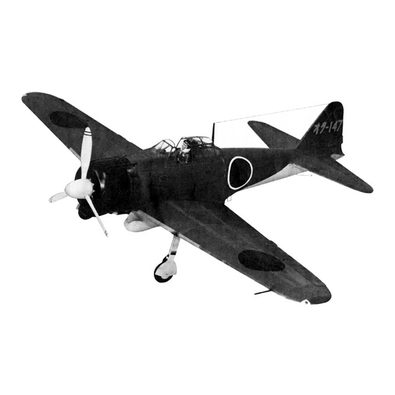
Summary of Contents for Top Flite A6M2 ZERO
- Page 1 BUILDING THE A6M2 ZERO Product Support (Do Not Remove From Department) TOP FLITE MODELS, INC...
- Page 2 Protect this investment by, 1. Re-checking all critical building points (center of gravity, We at Top Flite hope that you will find this model the most hingeing of control surfaces, strength of stress areas, etc ).
- Page 3 Trace pattern of Fin sheeting (3 pieces on each side) from Glue F-2A-2's to F-2A-1 and F-3A-2 to F-3A-1. Epoxy plans onto 1/16" x 2-7/8" balsa. Cut out and glue together F-1A(PLY), F-2A ASSEMBLY and F-3A ASSEMBLY all as shown above. Make two. together.
- Page 4 Laminate F-1B(PLY), F-2B and F-3B firewall as described for F-1A assembly. Set aside to dry. Epoxy F-19(PLY) doublers to insides of F-18 pieces. Glue formers F-5B. F-6B. F-7B, F-8B and P-9B into the slots Trim and glue a 1/8" x 7/8" x 30" STRIP to each side of in the two F-18 pieces.
- Page 5 Glue W-3B(PLY) and W-3C(PLY) to W-3 RIBS. Make one left hand and one right hand. Install elevator and rudder servos. Make and rudder pushrods. Glue W-5B(PLY) and W-5C(PLY) to W-5 RIBS. Make one Check all control surfaces for free and proper operation. Safety left hand and one right hand.
- Page 6 Leave last wing panel built pinned to work table. Join wing halves together using W-16(PLY) JOINERS and slow drying epoxy. Block up opposite wing panel for correct dihedral. Epoxy W-17(PLY)'s to W-16(PLY)'s. Glue W-21 to center of 3/4" face of 3/8" x 3/4" STRIP. Crack W-13(PLY) and W-14(PLY) in center to conform to angle of leading edge.
- Page 7 Temporarily center the REAR COWL on fuselage so that the mounting holes are at 45° to the vertical and horizontal center lines of the fuselage Mark location of holes with soft pencil Remove cowl and drill 1/8" DIA holes thru at marks Drill a 3/16"...
- Page 8 For a 16-page catalog plus a free MONOKOTE™ sample and prop chart, send request plus 50 cents to Top Flite © Top Flite Models, Inc. 1981 150308'...


Need help?
Do you have a question about the A6M2 ZERO and is the answer not in the manual?
Questions and answers