Table of Contents
Advertisement
™
WARRANTY.....
does not cover any component parts damaged by use or modification. In no case shall Top Flite's liability exceed the original cost of the purchased kit. Further, Top Flite
reserves the right to change or modify this warranty without notice. In that Top Flite has no control over the final assembly or material used for final assembly, no liability shall
be assumed nor accepted for any damage resulting from the use by the user of the final user-assembled product. By the act of using the user-assembled product the user
accepts all resulting liability. If the buyer is not prepared to accept the liability associated with the use of this product, the buyer is advised to immediately return this kit in
new and unused condition to the place of purchase.
Top Flite Models P.O. Box 788 Urbana, Il 61803
READ THROUGH THIS INSTRUCTION BOOK FIRST. IT CONTAINS IMPORTANT INSTRUCTIONS AND WARNINGS CONCERNING THE ASSEMBLY AND USE OF THIS MODEL.
Entire Contents © Copyright 2000
Top Flite Models guarantees this kit to be free of defects in both material and workmanship at the date of purchase. This warranty
Wingspan: 85 in [2159mm]
Wing Area: 1327 sq in [85.6 sq dm]
Weight: 20-22 lbs [9-10kg]
Wing Loading: 34.7-38.2 oz/sq ft
Length: 75.5 in [1918mm]
Technical Assistance Call (217)398-8970 productsupport@top-flite.com
[106-117 g/sq dm]
P47GP03
V1.0
Advertisement
Table of Contents

Related Manuals for Top Flite P-47D Thunderbolt


Summary of Contents for Top Flite P-47D Thunderbolt
- Page 1 In no case shall Top Flite‘s liability exceed the original cost of the purchased kit. Further, Top Flite reserves the right to change or modify this warranty without notice. In that Top Flite has no control over the final assembly or material used for final assembly, no liability shall be assumed nor accepted for any damage resulting from the use by the user of the final user-assembled product.
-
Page 2: Table Of Contents
Build the stabilizer and elevators ..10 detail, making the Top Flite Giant Scale Gold Edition Static display propeller ....57 Build the fin and rudder . -
Page 3: Decisions You Must Make
If this is your first giant scale project, get 6. If you are not already an experienced R/C pilot, ® instructions show a Great Planes Isolation Mount assistance with assembly and your first flights you must fly the model only with the help of a ™... -
Page 4: Landing Gear
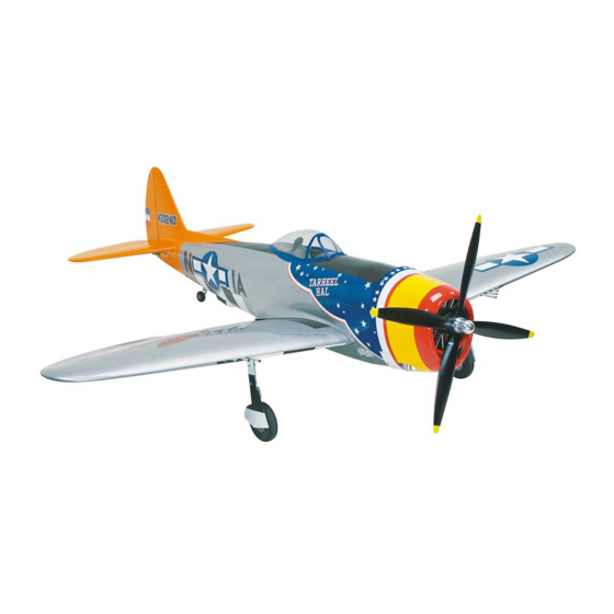
Be certain your servos, receiver, on/off switch TRIM SCHEME and charging system are compatible with your battery The outline of the Top Flite Gold Edition P-47 was pack. Use servo extension cords and Y-connectors The colorful “Tarheel Hal” trim scheme on the kit derived from three-view drawings and photos. -
Page 5: Scale Documentation
(HCAM2200). TOP is the We recommend Great Planes Pro CA and Epoxy. types of flying such as aggressive aerobatics or Top Flite brand, GPM is the Great Planes brand and racing, it is your responsibility to reinforce areas ®... -
Page 6: Covering Tools & Accessories
21st Century Cover Sock (COVR2702) 3/8" = 9.5mm 24" = 609.6mm 1/2" = 12.7mm 30" = 762mm We also use Top Flite 320-grit (TOPR8030, 4 sheets) 5/8" = 15.9mm 36" = 914.4mm and 400-grit (TOPR8032, 4 sheets) wet-or-dry 3/4" = 19mm sandpaper for finish sanding. -
Page 7: Important Building Notes
IMPORTANT BUILDING NOTES you are working on it. Similarly, move the former up means move the former toward the top of the fuselage even if the fuselage is upside-down when There are two types of screws used in this kit: you are working on it. -
Page 8: Die-Cut Patterns
DIE-CUT PATTERNS - 8 -... -
Page 9: Die-Cut Patterns
DIE-CUT PATTERNS - 9 -... -
Page 10: Get Ready To Build
GET READY TO BUILD because the ribs rest on jig tabs and do not contact the jigs should be the same length as the jig tab on each building board), cover the plan with film such as wax rib. Hold the ribs down using the rib jigs pinned to the paper or Great Planes Plan Protector. - Page 11 Note: The sketch is used to show the positioning and shape of the parts only. Determine the actual sizes of Top Flite selects balsa that is intended for sheeting, the parts by positioning the sheets over the stab and C. Turn the sheets over and apply glue to the though occasionally a few of these sheets may making marks with a ballpoint pen.
- Page 12 G. After the glue dries, sand the skins flat and even. Little sanding should be required. Note: Some modelers tend to sand the sheeting too much after it is applied to the structure, making thin spots where fingers can easily go through.
- Page 13 plan are intended to accommodate Robart large hinge points. If you plan to use flat hinges, the hinge blocks may need to be longer. ❏ 25. If necessary, trim the bottom of the elevator LE spar even with the bottom of the ribs. Glue the bottom elevator skins to the elevators.
-
Page 14: Build The Fin And Rudder
length shown on the plan, then glue it into position on Build the fin and rudder the front of the ribs. ❏ 1. Place the fin and rudder plan over your building ❏ 6. Join the die-cut 1/8" balsa rudder LE spar to the board. -
Page 15: Hinge The Elevators And Rudder
❏ ❏ 13. Cut eight 1-1/2" long hinge blocks from a 1/4" 21. Cut the fin tip and the rudder tip from the 3/4" Hinge the elevators and rudder x 1/2" x 30" balsa stick. Glue the hinge blocks to the x 1-1/2"... -
Page 16: Build The Fuselage
❏ on this assembly will be referred to as F-2B. Sand 2. Use a 3/16" brass tube sharpened on the end BUILD THE FUSELAGE F-2B flat and even. or a 3/16" drill bit to drill holes for your hinges (not supplied) at the marks you made. - Page 17 ❏ over the plan. An accurate way to do this is to place 6. Use medium CA to glue TR, RUC and LUC to F-1 one on top of the other with the grooves opposed, making certain F-1 is perpendicular to the building then use a razor saw and a miter box (or a table belt board.
-
Page 18: Sheet The Fuse Top
Now is the time to decide whether you are going to build the razorback or the bubble canopy version. Steps beginning with a “B” are for the “bubble canopy” and steps beginning with an “R” are for the razorback. Steps with neither “B” nor “R”... - Page 19 ❏ an additional 3/32" x 4" x 36" balsa sheet for the left 10. Remove the fin. Mix up a batch of 30-minute side. Glue the first sheet to the right side of the fuse. epoxy. For additional strength, add Great Planes Do not glue the sheeting to the stab saddle.
- Page 20 ❏ blends with the curvature of the formers (refer to the B16. Glue a 1/4" x 1/4" x 30" balsa stringer into the cross section on the plan). notches in the tops of the turtledeck. ❏ R20. Sheet both sides of the turtle deck from the ❏...
-
Page 21: Build The Fuse Bottom
❏ 23. Take out all the T-pins and remove the fuse top Build the fuse bottom from your building board. Place the fuselage upside- down in a suitable building stand (such as a Robart ® Before you proceed, remember that the embossed Super Stand II, ROBP1402, seen in following photos). - Page 22 ❏ 9. Slide the 48" long guide tubes through the holes through the main side stringers to accommodate in the formers and out the exit slots you just cut in the the inner doors, construct the doors, then paint back of the fuse. Note that there are two tubes on the them to match the trim scheme.
-
Page 23: Sheet The Fuse Bottom
Sheet the fuse bottom ❏ 1. The same as you did before sheeting the top of the fuse, glue leftover 3/32" balsa to both sides of former 6 to support the sheeting where it will be spliced together. ❏ 2. You can wait until later, but now would be a good time to connect air lines to the air cylinder on ❏... -
Page 24: Build The Dorsal Fin
Note: The opening shown in the photo is not large enough to completely remove the tail gear from the fuselage. However, the gear can be dismounted and maneuvered enough to attach the air lines and pull-pull cables while it is still partially inside the fuse. -
Page 25: Intercooler Doors
sheeting blends the fin to the dorsal fin in a nearly seamless transition. Glue the dorsal fin sheeting into position on both sides. ❏ 5. Use balsa filler to blend the dorsal fin to the fin and to the fuselage. While you’re at it, make a small fillet around the fin and stab, blending them to each other and to the fuse. -
Page 26: Mount The Engine
❏ a straightedge to draw lines connecting the four Mount the engine 7. Test fit the doublers to the crutches in the fuse, inner punch marks. Center the engine mount on the then test fit the firewall. Be certain the firewall will fit cross marks, then mark and drill the appropriate size all the way into the notches of the crutches. -
Page 27: Hook Up The Controls
rubber). Be certain to position the tank so it will not interfere with your throttle pushrod. As you can see in the photo, we mounted our tank off to the right side of the fuse to accommodate the throttle pushrod. The tank should be mounted securely, yet be removable for inspection and servicing after the model is completed and you’ve been flying it for a while. - Page 28 Refer to this photo to hook up the servos. ❏ 7. Mount the elevator control horn to the elevator with four #4 x 3/8" screws. Mount the other control ❏ horn and pushrod to the other elevator the same way. 10.
-
Page 29: Finish The Cockpit
❏ 15. Mount the rudder servo in the servo tray. Finish the cockpit Connect the rudder pushrod to the rudder servo with a split coupler, an additional piece of wire cut from a Skip the first two steps if you are not going to install .095”... -
Page 30: Build The Wing
BUILD THE WING Preparation ❏ 1. Cut the right wing panel plan from the rest of the plan and lay it on your flat building board. Cover the plan with Great Planes Plan Protector or wax paper. ❏ 2. Make two spar doublers by cutting a 1/4" x 3/8" x 42"... -
Page 31: Make The Wing Skins
❏ 8. Drill a 1/16" hole through the punch mark in both die-cut 1/8" plywood forward spar joiner braces (refer to the die drawings on pages 8 & 9 to locate the forward spar joiner brace). ❏ 9. If you wish to plan ahead a little, you can use a 5/32"... -
Page 32: Build The Wing Panels
❏ ❏ Build the wing panels 4. Use some of the 1/4" x 1/4" rib jigs leftover from building the tail surfaces to hold ribs 2A, 2B, 2.5, 3 and 3.5 over their position on the plan. Use rib We’ll start with the right wing panel first. jigs on other ribs as necessary to help hold the wing panel firmly to your building board. - Page 33 ❏ ❏ 16. Make gussets from leftover 1/8" balsa and glue them to the forward dowel plate as shown on the plan. ❏ ❏ 17. Drill 1/4" holes through the 1/4" x 2" x 7-3/4" plywood wing bolt plate where shown on the plan. Note: Though the holes are not shown in the wing bolt plate in the following photos, yours should now be drilled.
-
Page 34: Sheet The Top Of The Wing Panels
❏ ❏ Sheet the top of the wing panels 9. Use the top and bottom flap skin patterns on the plan to make the top and bottom flap skins ❏ ❏ from two 3/32" x 4" x 24" balsa sheets. The bottom 1. -
Page 35: Mount The Landing Gear
❏ (providing a 1/16" gap between the flap skin and the Mount the landing gear 4. Once you have established the exact positioning inner TE sheet—refer to the photo in the following of the landing gear rails and test fitted the gear, use ❏... -
Page 36: Join The Wing Panels
the notches in the ribs. Make certain your servos will joiners are birch ply and one of the joiners is lite-ply.The fit between the rails when mounted to the 1/2" x 1" x lite-ply joiner goes in the middle. It is best to clamp the 1"... -
Page 37: Sheet The Bottom Of The Wing
❏ ❏ joiners in the wing. If this is the case, stick a piece of 5. Once you have achieved a good fit of the wing 2. Cut eight 1-1/4" long hinge blocks for the Great Planes Adhesive Backed 80-grit sandpaper to a panels with the wing joiner and the wing bolt plate, aileron hinges from the 1/2"... -
Page 38: Build The Ailerons
❏ support the wing. The tip jigs are positioned under Refer to this sketch for the following two steps. 7. Cut the 5/16" x 15" dowel into two 6-7/8" wing ribs 12. If necessary, lightly tack glue the jigs to the dowels. - Page 39 ❏ ❏ sketch. Trim the bottom wing sheeting even with the 12. Mark the centerlines of both the aileron LE inner TE’s. Bevel the balsa portion of the top wing and the outer TE spar, then drill holes or cut slots for sheeting to the top ply sheeting.
-
Page 40: Build The Flaps
❏ ❏ ❏ ❏ 15. Center the right aileron and securely tape it Build the flaps 4. Remove the flap horn. True the ends of the to the wing. This will help with alignment and shaping flap LE’s even with the ends of the flap. of the wing tip. - Page 41 inner TE spar. Use a 3/16" brass tube sharpened at the end or a 3/16" drill bit to drill the hole for the hinge. Drill the remaining holes in the wing the same way. ❏ 10. Use a straightedge and a ballpoint pen to ❏...
-
Page 42: Make The Servo Hatches
❏ Make the servo hatches 3. Securely tape the hatch cover into position. Drill 1/16" holes through the hatch cover and the servo rails. Start with the right aileron hatch... ❏ 4. Remove the servo hatch and enlarge the holes in the hatch cover only with a 3/32"... -
Page 43: Finish The Wheel Wells
❏ ❏ 2. Use 30-minute epoxy to glue the servo 6. Use four #4 x 1/2" screws to mount a control mounting blocks to the inside of the hatch covers. Be horn to the mounting plate. certain the servos are positioned on the covers ❏... - Page 44 ❏ ❏ ❏ 4. Glue strips of leftover 1/32" plywood under the 6. Make wheel cover mounts by drilling 1/2" 9. Trim the ends of the blocks so the covers will align balsa sheeting inside the landing gear cutouts to holes through a 1/2"...
-
Page 45: Final Construction
We made the machine guns on our prototype after the wing was covered, but they are easier to make now, before the wing is covered. ❏ 2. Temporarily position the wing dowels in the wing, then glue the center LE (prepared earlier) into position. -
Page 46: Build The Wing Fillets
❏ wing cradle where former 5 and the crutch meet. 10. Remove the wing from the fuse. Enlarge the Build the wing fillets Draw a 6" line on the fuse as shown. This will be a holes in the wing bolt plate in the wing with a 17/64" ❏... -
Page 47: Build The Belly Pan
❏ 9. Use lightweight balsa filler to build up a smooth fillet covering the balsa sheeting and tri stock and blending the fuse to the fillet base. The more time you spend applying and smoothing the filler, the less sanding you will have to do after it dries. ❏... -
Page 48: Assemble The Cowl
❏ Refer to this photo for the following four steps. sheets that cover the belly pan between the bottom of 13. Apply lightweight balsa filler where needed to the wing and the middle of the first stringer. Test fit one blend the belly pan to the wing. - Page 49 ❏ test fit them to the cowl. When a good fit is achieved, 2. Use a bar sander with 80-grit sandpaper to true glue the cowl flaps to the cowl, and then to each other. the edges of the cowl pieces so they fit well. Clean the plastic with alcohol, then thoroughly roughen the inside edges of all the joints with coarse sandpaper.
- Page 50 ❏ ❏ 9. Once you have positioned the cowl mounts and 17. Test fit, then temporarily tack-glue the baffle the cowl rings, remove one of the cowl ring sections, into the cowl against the lip that joins the cowl front add medium CA, then carefully reposition the cowl to the sides.
-
Page 51: Balance The Airplane Laterally
❏ 24. Refer to the photo on the box and at step 4 of FINISHING Scale Details for placement of the oil cooler shutters, then shape the oil cooler shutters as you did the Final Preparations turbo-supercharger cover. While some modelers prefer to mount the receiver and battery pack before covering the model (and before the C.G. -
Page 52: Painting
Everything that was painted on this model was tested for compatibility. Now your LustreKote is ready painted with Top Flite LustreKote (except for the A. Apply at least two coats of primer, allowing to dry to spray through your airbrush. -
Page 53: Covering
Mask off the inside of the canopy to protect it from overspray. ❏ 1. Use a dust brush, compressed air or a Top Flite ❏ Tack Cloth to remove balsa dust from the model. 5. Paint the canopy frame. - Page 54 This is a total “eyeball” procedure, so mark the stripes directly on the fuse. These will are cut from red MonoKote using a Top Flite Smart taking your time now will show when your model serve as guidelines for positioning the MonoKote Stripe ™...
-
Page 55: Cover The Wing
All the rest of the panel lines are made with the Panel Line Apply the decals Pen. Use a Top Flite Smart Stripe (TOPR2420) to cut FINAL ASSEMBLY panel lines from black MonoKote. -
Page 56: Hook Up The Controls
Secure all connections with vinyl tape, heat shrink 2. Carefully cut the covering just inside the line built one) and a pilot. We used the Top Flite 1/5-scale tubing, or special clips intended for that purpose. you marked. Peel the covering off. -
Page 57: Mount The Canopy
hobby knife with a sharp #11 blade to carefully cut a 1/16" strip of covering from the fuse. Remove the covering, exposing the bare balsa. This will allow the canopy to be securely attached to the fuse—not just to the covering. ❏... -
Page 58: Get Your Model Ready To Fly
wood blade from a block of basswood and using it as a leading edge at the location of rib 5 (not alongside attach weight to the cowl. It is not intended to support mold to vacuum-form four front halves and four back the fuse). -
Page 59: Set The Control Surface Throws
We use a Top Flite Precision Magnetic Prop Balancer ™ (TOPQ5700) in the workshop and keep a Great CONTROL SURFACE THROWS... -
Page 60: Engine Safety Precautions
To stop a glow engine, cut off the fuel supply by RADIO CONTROL ENGINE SAFETY PRECAUTIONS closing off the fuel line or following the engine manufacturer’s recommendations. Do not use hands, 1. I will have completed a successful radio Failure to follow these safety precautions may fingers or any other body part to try to stop the equipment ground check before the first flight of a result in severe injury to yourself and others. - Page 61 Section 3.0: Safety Check Generally, it is recommended that no attempt should be Additional General Recommendations 3.4 Flight Testing: All Giant Scale R/C aircraft are to made to fly a radio controlled model aircraft with a have been flight tested and flight trimmed with a gasoline engine in which the model aircraft weight Servos need to be of a rating capable to handle the minimum of six flights before the model is allowed to...
-
Page 62: Check List
Y-connectors or servo extensions, and check list! ). the connection between your battery pack The Top Flite Giant P-47 is a great-flying scale and the on/off switch with vinyl tape, heat warbird that flies smoothly and predictably. It does shrink tubing or special clips suitable for ❏... -
Page 63: Takeoff
For reassurance and to keep an eye on other traffic, To initiate a landing approach, make your final turn Fuel mixture adjustment it is a good idea to have an assistant on the flight line toward the runway (into the wind) keeping the nose with you. - Page 64 Here is the Engineering and Performance data for a 3-VIEW DRAWING P-47-D-25 (similar to the one on our kit box cover): Use this layout for trim scheme planning only. Model: P-47D-25-RE Not suitable for scale Quantity built: 385 documentation. AAF Serial numbers: 42-26389 to 42-26773 Engine: Pratt &...
Need help?
Do you have a question about the P-47D Thunderbolt and is the answer not in the manual?
Questions and answers