
Related Manuals for Intek M-150 PLUS


Summary of Contents for Intek M-150 PLUS
- Page 1 M-150 PLUS MULTI STANDARD PROGRAMMABLE 27 MHz CB MOBILE TRANSCEIVER OWNER'S MANUAL MANUALE DI ISTRUZIONI...
- Page 2 (to EC Directive 99/5-89/336-93/68-73/23) DECLARATION OF CONFORMITY With the present declaration, we certify that the following products : INTEK M-150 PLUS comply with all the technical regulations applicable to the above mentioned products in accordance with the EC Directives 73/23/EEC, 89/336/EEC and 99/5/EC.
-
Page 3: Table Of Contents
With a correct use of the product in accordance with the operating method described in this manual, the product will offer a trouble free use for many years. INTEK is constantly engaged to develop and provide quality products meeting the customers requirements, however any suggestion or comments on this product that might help us to improve quality are warmly welcome. -
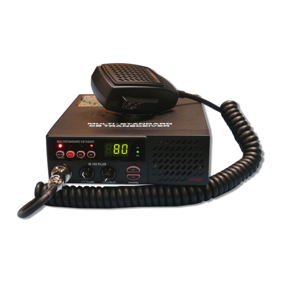
Page 4: Controls, Indicators And Operation
Controls, Indicators and operation Front panel MULTISTANDARD CB RADIO AM/FM UK/CEPT M-150 PLUS OFF/VOLUME AS/SQUELCH CHANNEL AM/FM and UK/CEPT Key AM/FM SELECTOR Shortly press the AM/FM Key (1) to select the AM or FM operating mode in both RX and TX. The AM/FM operating mode selection is possible only if it is allowed the programmed frequency band, otherwise the selection is not possible. - Page 5 Controls, Indicators and operation EMG Indicator This red color LED indicator is lighted when one of the pre-programmed Emergency Channels has beel selected. ANL Indicator This red color LED indicator is lighted when the ANL (Automatic Noise Limiter) function is enabled. RB Indicator This red color LED indicator is lighted when the Roger Beep function is enabled.
- Page 6 Controls, Indicators and operation ANL/PA key ANL (Automatic Noise Limiter) FUNCTION Shortly press the ANL/PA (16) key to enable the ANL (Automatic Noise Limiter) function, in order to reduce electric or electromagnetic noise or interference on the used channel. The LED indicator (5) is lighted to confirm that the ANL function is enabled.
- Page 7 Controls, Indicators and operation Microphone PTT (Push-to-Talk) Key Transmitter key. Press the PTT (22) key to transmit and release it to return to the receive mode. MICROPHONE Plug 6-pole microphone plug with locking ring nut, to be connected to the microphone connector (17) located on the front side of the radio.
-
Page 8: Installation
Installation Installation Before installing the main unit in the vehicle, check and select the most convenient location, in order that the radio will be easy to reach and comfortable to operate, without disturbing or interfering with the vehicle drive. Use the supplied bracket and hardware to install the radio. -
Page 9: Frequency Bands Table - User Information
Frequency bands table - User Information Frequency Bands Table The transceiver INTEK M-150 PLUS includes an advanced multi-standard programmable circuit, which allows to program different frequency bands, specifications and operating modes, in conformity with the regulations in the country where the product is used. 8 programmable frequency bands are available, as per the below table :... -
Page 10: Frequency Band Selection / Programming
Frequency band selection / Programming Frequency Band Selection / Programming The radio must be programmed and used exclusively on a frequency band allowed in the country where the product is used. It is possible to program a different frequency band, as per the following procedures : Switch off the radio. -
Page 11: Specifications
Specifications Specifications General Channels Refer to the frequency bands table at page 7 Frequency range 27 MHz Citizen Band Frequency control P.L.L. Operatine temperature -10°/+55°C DC input voltage 13.2Vdc ±15% Size 180 (L) x 50 (A) x 153 (P) mm Weight 950 gr. - Page 12 CE (CEPT 40CH FM 4W). Congratulazioni ! Congratulazioni per aver scelto ed acquistato un prodotto di qualità INTEK. Questo ricetrasmettitore dispone di numerose funzioni avanzate e vari dispositivi, pertanto è assolutamente necessario leggere attentamente questo manuale di istruzioni prima di utilizzare l' apparecchio.
- Page 13 Descrizione dei comandi, indicatori e funzionamento Pannello frontale MULTISTANDARD CB RADIO AM/FM UK/CEPT M-150 PLUS OFF/VOLUME AS/SQUELCH CHANNEL Tasto AM/FM - UK/CEPT SELETTORE AM/FM Premendo brevemente questo tasto verrà selezionato il modo operativo AM o FM in ricezione e trasmissione. La selezione del modo AM/FM è...
- Page 14 Descrizione dei comandi, indicatori e funzionamento Indicatore EMG Questo indicatore LED luminoso di colore rosso è acceso quando è in uso uno dei canali di emergenza. Indicatore ANL Questo indicatore LED luminoso di colore rosso è acceso quando è abilitato il dispositivo ANL (Automatic Noise Limiter).
- Page 15 Descrizione dei comandi, indicatori e funzionamento Tasto ANL / PA FUNZIONE ANL (Automatic Noise Limiter) Premendo brevemente il tasto ANL (16) viene inserito il dispositivo ANL (Automatic Noise Limiter) che permette la riduzione dei disturbi radio elettrici ed elettromagnetici sul canale in uso. L' indicatore LED (5) sarà...
- Page 16 Descrizione dei comandi, indicatori e funzionamento Microfono Tasto PTT (Push-to-Talk) Tasto di trasmissione. Premere per trasmettere e mantenere premuto durante la trasmissione e rilasciare per ritornare in modalità ricezione. Connettore microfono Connettore del microfono a 6 poli con ghiera di fissaggio, da collegarsi alla apposita presa (17) sul pannello frontale. IMPORTANTE ! Non tentare mai di aprire il contenitore del ricetrasmettitore.
- Page 17 Installazione e collegamenti elettrici Installazione E' necessario verificare e localizzare sul veicolo la posizione più opportuna ove installare l' apparato, in modo che sia pratico e confortevole l' utilizzo dello stesso e che l' ubicazione del ricetrasmettitore non sia in nessun modo di ostacolo alla guida del veicolo.
- Page 18 Tabella bande di frequenza Il ricetrasmettitore INTEK M-150 PLUS dispone di un avanzato circuito multi-standard programmabile, che consente di programmare la banda di frequenza, i parametri e i modi operativi in conformità con le norme del paese in cui viene utilizzato l’...
- Page 19 Selezione / programmazione della banda di frequenza Selezione / programmazione della banda di frequenza Il ricetrasmettitore deve essere programmato e utilizzato esclusivamente su una banda di frequenza ammessa nel paese in cui viene utilizzato l’ apparecchio. Per programmare la banda di frequenza, eseguire la seguente procedura : Spegnere il ricetrasmettitore.
- Page 20 Caratteristiche tecniche Caratteristiche tecniche Generali Canali Vedere tabella bande di frequenza a pag. 16 Gamma di frequenza 27 MHz Banda Cittadina Controllo di frequenza P.L.L. Temperatura di lavoro -10°/+55°C Tensione di alimentazione 13.2Vdc +/-15% Dimensioni 153 (L) x 50 (A) x 180 (P) mm Peso 950 gr.
- Page 21 Note - 19 -...
-
Page 22: Table Of Restrictions On The Use Of Cb Transceivers
Table of restrictions on the use of CB transceivers COUNTRY CB Introd. Use restrictions and other comments Settings AUSTRIA Not allowed 40 CH - 4W FM - Individual license is required BELGIUM 40 CH - 1W AM - Individual license is required DENMARK 40 CH - 4W FM - Free use 40 CH - 4W FM - Free use... -
Page 23: Vco Diagram
VCO Diagram - II -... -
Page 24: Pcb - Main Board & Front Board
PCB - Main Board & Front Board M-150 PLUS / M-760 PLUS - III -... - Page 25 PCB - Main Board & Front Board M-150 PLUS / M-760 PLUS - IV -...
-
Page 26: Diagram
Diagram - V -... - Page 27 Diagram - VI -...
-
Page 28: Block Diagram
Block Diagram - VII -... - Page 29 Block Diagram - VIII -...
- Page 30 Notes...
- Page 31 Notes...
Need help?
Do you have a question about the M-150 PLUS and is the answer not in the manual?
Questions and answers