Table of Contents
Advertisement
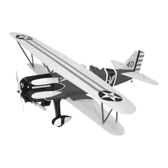
Wingspan: Top Wing - 76 in [1930mm]
Bottom Wing - 63 in [1600mm]
Wing Area: Top Wing - 852 sq in [55 dm
Bottom Wing - 589 sq in [38 dm
Weight: 14–16 lb [6348 – 7255 g]
Wing Loading: 22–26 oz/sq ft [67-79 g/dm
Length: 59.75 in [1518mm]
Radio: 4-channel with 5 servos
Engine: .91-1.08 cu in [15-17.5cc] two-stroke,
.91-1.20 cu in [19.5-23cc] four-stroke
Great Planes
®
Model Manufacturing Co. guarantees this kit to be free from defects in both material and workmanship at the date of
purchase. This warranty does not cover any component parts damaged by use or modification. In no case shall Great Planes' liability
exceed the original cost of the purchased kit. Further, Great Planes reserves the right to change or modify this warranty without notice.
In that Great Planes has no control over the final assembly or material used for final assembly, no liability shall be assumed nor
accepted for any damage resulting from the use by the user of the final user-assembled product. By the act of using the user-assembled
product, the user accepts all resulting liability.
If the buyer is not prepared to accept the liability associated with the use of this product, the buyer is advised to return this
kit immediately in new and unused condition to the place of purchase.
To make a warranty claim send the defective part or item to Hobby Services at the address below:
Include a letter stating your name, return shipping address, as much contact information as possible (daytime telephone number, fax
number, e-mail address), a detailed description of the problem and a photocopy of the purchase receipt. Upon receipt of the package
the problem will be evaluated as quickly as possible.
READ THROUGH THIS MANUAL BEFORE STARTING
CONSTRUCTION. IT CONTAINS IMPORTANT WARNINGS
AND INSTRUCTIONS CONCERNING THE ASSEMBLY
AND USE OF THIS MODEL.
© Copyright 2005
INSTRUCTION MANUAL
2
]
2
]
2
]
WARRANTY
Hobby Services
3002 N. Apollo Dr. Suite 1
Champaign IL 61822 USA
Champaign, Illinois
(217) 398-8970, Ext 5
airsupport@greatplanes.com
GPMZ0180 for GPMA1219 V1.1
Advertisement
Table of Contents

Subscribe to Our Youtube Channel
Related Manuals for GREAT PLANES P-6E HAWK


Summary of Contents for GREAT PLANES P-6E HAWK
-
Page 1: Instruction Manual
Further, Great Planes reserves the right to change or modify this warranty without notice. In that Great Planes has no control over the final assembly or material used for final assembly, no liability shall be assumed nor accepted for any damage resulting from the use by the user of the final user-assembled product. -
Page 2: Table Of Contents
TABLE OF CONTENTS INTRODUCTION INTRODUCTION ...............2 The P-6E Hawk has a long and colorful history in both the IMAA..................2 U.S. military and abroad. You will thoroughly enjoy the wide SAFETY PRECAUTIONS..........2 range of capabilities of this plane as well as its good looks. -
Page 3: Additional Items Required
This is the list of hardware and accessories required to finish show any signs of wear or fatigue. the P-6E Hawk. Order numbers are provided in parentheses. ❏ 7. If you are not already an experienced R/C pilot, you... -
Page 4: Optional Supplies & Tools
Here is a list of optional tools mentioned in the manual that will help you build the P-6E Hawk ARF. • The P-6E Hawk ARF is factory-covered with Top Flite ® MonoKote ®... -
Page 5: Kit Inspection
If any parts are missing or are not of acceptable quality, or if you need assistance with assembly, contact Great Planes Product Support. When reporting defective or missing parts, use the part names exactly as they are written in the Kit Contents list on this page. -
Page 6: Ordering Replacement Parts
ORDERING REPLACEMENT PARTS Replacement parts for the P-6E Hawk ARF are available using the order numbers in the Replacement Parts List that follows. The fastest, most economical service can be provided by your hobby dealer or mail-order company. Parts may also be ordered directly from Hobby Services, but full retail prices and shipping and handling charges will apply. -
Page 7: Preparations
PREPARATIONS ❏ 1. If you have not done so already, remove the major parts of the kit from the box and inspect for damage. If any parts 1" are damaged or missing, contact Product Support at the [25mm] address or telephone number listed in the “Kit Inspection” section on page 5. -
Page 8: Join The Top Wing Panels
❏ 6. To check that the joiners are properly installed, position Join the Top Wing Panels the top wing upside-down on your flat building surface. The wing should lay flat. If it does not, remove the forward wing ❏ ❏ 1. -
Page 9: Install The Bottom Wing
Install the Bottom Wing ❏ 2. After the glue has cured, test fit the wing joiner into the bottom wing panels. Note that the wing joiner is angled to provide dihedral in the bottom wing. Also insert the smaller ❏ hardwood trailing edge wing joiner. -
Page 10: Install The Stabilizer And Fin
INSTALL THE STABILIZER AND FIN Install the Stabilizer and Elevator ❏ 1. Remove the two elevators from the stabilizer. ❏ 5. Measure the distance from the tip of the stabilizer to the center of the fuselage at the firewall. Adjust the position of the stabilizer until they are equal. - Page 11 ❏ 8. Trim the covering from over the slot at the lower leading edge of the rudder. Test fit the tail gear wire in the slot. ❏ 4. Use a canopy scissors or hobby knife to trim the plastic fin cover along the molded cut lines. Trial fit the cover over the fin.
-
Page 12: Install The Main Landing Gear
4-40 set screw. Make sure to use thread lock on the set screw to prevent it from coming loose. Did you know? ..The P-6E Hawk was of mixed construction. The wings had ❏ 3. Use a hacksaw or cutoff wheel on a rotary tool to cut wooden spars and ribs, and the the two 3/16"... -
Page 13: Install The Engine
INSTALL THE ENGINE Mount the Engine ❏ ❏ 5. Install a 4" [102mm] foam wheel on the axle followed by a 3/16" [4.8mm] wheel collar. Secure the wheel collar to the axle with a 6-32 set screw. Make sure to use thread lock on the set screw and tighten the set screw against the flat spot on the axle. -
Page 14: Mount The Cowl
Install a washer should be from the firewall. Mark the location of the propeller on the engine. engine on the mount. The Great Planes Dead Center ™ Hole Locator (GPMR8130) works well for this. Drill through the marks you have made on the engine mount with a #29 or 9/64"... -
Page 15: Install The Fuel Tank
❏ 2. Carefully bend one of the long tubes so that it will angle up toward the top of the fuel tank when inserted. Do not kink the tube. Mark a “P” on the outside of the front plate to designate pressure. ❏... -
Page 16: Install The Throttle Servo
❏ 6. Connect the correct fuel line to the carberator and the fuel line plug to the fill line. The pressure line will be connected to the muffler once the cowl has been installed. ❏ 7. Use a #64 rubber band to secure the aft end of the fuel tank to the former. -
Page 17: Finish Assembling The Cowl
❏ ❏ 7. Install a brass screw-lock pushrod connector on the throttle 9. Thread a nylon clevis 14 turns onto the 2-56 x 17" servo arm. Secure it with a nylon keeper. Thread a 4-40 x 1/4" [432mm] metal pushrod. Slide a silicone clevis retainer over [6.4mm] socket head cap screw in the pushrod connector. -
Page 18: Install The Radio System
Did you know? ..On July 10, 1931, the first order for 46 of the P-6E Hawks was placed. Of the 656 Hawks built, more than 1/3rd were exported to foreign countries. The lifespan in the U.S. Army Air Corp was short due to the development of the Boeing P-26A monoplane. - Page 19 ❏ ❏ 3. On the left side of the fuselage, slide one wire into the 6. Center the rudder and the rudder servo. Then, install opening closest to the back of the fuselage. Install a large the servo arm. Install a metal solder clevis in the last hole in nylon control horn onto the clevis.
- Page 20 C. Apply a small drop of solder flux to the joint. D. Heat the area to be soldered. Apply solder to the heated area. The metal must get hot enough to melt the solder and the solder must flow into the joint. Do not melt the solder by touching it to the soldering iron.
-
Page 21: Install The Aileron Servos & Pushrods
plate in the aileron. Mark the location of the mounting holes Install the Aileron Servos and Pushrods onto the aileron. Drill a 1/16" [1.6mm] hole on the marks, drilling through the plywood plate but not through the top of ❏ ❏ 1. -
Page 22: Install The Top Wing
INSTALL THE TOP WING ❏ 1. Attach the lower wing to the fuselage with the 1/4-20 nylon wing bolts. ❏ ❏ 2. Locate eight metal cabane mounting brackets. Set four brackets for the top wing to the side. We will be installing the brackets on the bottom wing first. -
Page 23: Finish The Fuselage
❏ 10. Place the top wing onto the “N” struts. Attach the top FINISH THE FUSELAGE wing to the “N” struts with 4-40 x 1/2" [13mm] socket head cap screws, #4 washers and 4-40 nylon lock nuts the same way you installed the strut to the lower brackets. Build the Carrying Handle This kit comes with a convenient carrying handle for the fuselage and the struts. - Page 24 ❏ ❏ 4. Glue the two parts shown onto one of the plywood 7. Place the two “N” struts into the handle. Put the handle carrying handle parts. Make sure the four holes are aligned. top onto the part of the handle holding the struts and place the completed handle on top of the cabanes.
-
Page 25: Assemble The Nose Weight Box
Assemble the Nose Weight Box Our prototype model required the addition of nose weight with engines at the bottom end of the recommended range. We have included a box for you to easily add the weight that most likely will be needed. ❏... -
Page 26: Optional Flying Wire Installation
Optional Flying Wire Installation The photos on the box show optional flying wires installed on the plane. The materials we used for this are not included in the kit but are readily available at any fabric store for less than $10.00. - Page 27 ❏ 6. Continue threading the cord through the aft hole in the trailing edge of the stab on the opposite side of the fuselage and back down to the aft bottom of the fuselage. ❏ 7. At this point you will have to start stretching the elastic to complete the positioning of the elastic cord.You may need to trim a little off of the end of the cord to remove any slack before gluing it in the aft hole of the fuselage.
- Page 28 ❏ ❏ ❏ ❏ 11. Bring the elastic cord around the top of the forward 14. Bring the elastic cord around the top of the aft strut strut and pull it back toward the fuselage. Glue the cord into and pull it back toward the fuselage. Glue the cord into the the hole next to the hole you started with.
-
Page 29: Apply The Decals
❏ 19. Cut four pieces of elastic cord 4-1/2" [114mm] long. Glue a cord into each of the four holes. Stretch the cord to the top of the cabane and glue the cord to the cabane with a small drop of CA. Apply the Decals ❏... -
Page 30: Get The Model Ready To Fly
Note: The throws are measured at the widest part of the covering, and the radio system. The P-6E Hawk ARF is a elevators, rudder and ailerons. short-coupled airplane, making it nearly impossible to balance without the addition of some nose weight. -
Page 31: Balance The Model Laterally
PREFLIGHT Identify Your Model No matter if you fly at an AMA sanctioned R/C club site or if you fly somewhere on your own, you should always have your name, address, telephone number and AMA number on or inside your model. It is required at all AMA R/C club flying sites and AMA sanctioned flying events. -
Page 32: Balance The Propellers
™ the propeller may throw such material in your face or eyes. (TOPQ5700) in the workshop and keep a Great Planes Fingertip Prop Balancer (GPMQ5000) in our flight box. • Keep your face and body as well as all spectators away from the plane of rotation of the propeller as you start and run the engine. -
Page 33: Ama Safety Code ( Excerpts )
IMAA SAFETY CODE ( EXCERPTS EXCERPTS Since the P-6E Hawk ARF qualifies as a “giant-scale” model Read and abide by the following excerpts from the Academy and is therefore eligible to fly in IMAA events, we’ve included of Model Aeronautics Safety Code. For the complete Safety excerpts from the IMAA Safety Code. -
Page 34: Check List
CHECK LIST FLYING ❏ 1. Fuelproof all areas exposed to fuel or exhaust residue Fuel Mixture Adjustments such as the cowl mounting blocks, wing saddle area, etc. ❏ 2. Check the C.G. according to the measurements provided in the manual. A fully cowled engine may run at a higher temperature than ❏... -
Page 35: Flight
But always stay in control and fly in a safe manner. GOOD LUCK AND GREAT FLYING! Take it easy with the P-6E Hawk ARF for the first few flights, gradually getting acquainted with it as you gain confidence. Adjust the trims to maintain straight and level flight. After... - Page 36 BUILDING NOTES Kit Purchased Date: _______________________ Date Construction Finished: _________________ Where Purchased:_________________________ Finished Weight: __________________________ Date Construction Started: __________________ Date of First Flight: ________________________ FLIGHT LOG...
Need help?
Do you have a question about the P-6E HAWK and is the answer not in the manual?
Questions and answers