Table of Contents
Advertisement
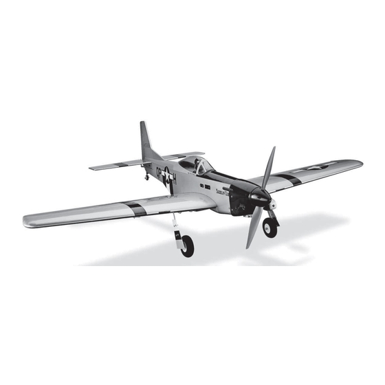
SPECIFICATIONS
Wingspan:
52 in [1320mm]
Length:
42.5 in [ 1080mm]
550 in
2
[35.5 dm
Wing Area:
WARRANTY
Great Planes
®
Model Manufacturing Co. guarantees this kit to
be free from defects in both material and workmanship at the
date of purchase. This warranty does not cover any component
parts damaged by use or modification. In no case shall Great
Planes' liability exceed the original cost of the purchased kit.
Further, Great Planes reserves the right to change or modify this
warranty without notice.
In that Great Planes has no control over the final assembly or
material used for final assembly, no liability shall be assumed nor
accepted for any damage resulting from the use by the user of
the final user-assembled product. By the act of using the
user-assembled product, the user accepts all resulting liability.
If the buyer is not prepared to accept the liability associated
with the use of this product, the buyer is advised to return
READ THROUGH THIS MANUAL BEFORE STARTING CONSTRUCTION. IT CONTAINS IMPORTANT
INSTRUCTIONS AND WARNINGS CONCERNING THE ASSEMBLY AND USE OF THIS MODEL.
© 2014 Great Planes Model Mfg. A subsidiary of Hobbico,
INSTRUCTION MANUAL
Weight:
5– 5.75 lb
[2270– 2610 g]
Wing
21– 24 oz/ft
2
]
Loading:
[64– 73 g /dm
®
Inc.
Radio:
Minimum four channel
Engine:
.46-.55 cu in (7-9 cc) 2-stroke
or .70 (11.5 cc) 4-stroke
2
2
]
Electric:
RimFire 32, 45 amp ESC
this kit immediately in new and unused condition to the
place of purchase.
To make a warranty claim send the defective part or item to
Hobby Services at the address below:
Hobby Services
3002 N. Apollo Dr. Suite 1
Champaign IL 61822 USA
Include a letter stating your name, return shipping address, as
much contact information as possible (daytime telephone
number, fax number, e-mail address), a detailed description of
the problem and a photocopy of the purchase receipt. Upon
receipt of the package the problem will be evaluated as quickly
as possible.
(217) 398-8970, Ext 5
airsupport@greatplanes.com
Champaign, Illinois
GPMA1208
Advertisement
Table of Contents

Subscribe to Our Youtube Channel
Related Manuals for GREAT PLANES P-51 MUSTANG


Summary of Contents for GREAT PLANES P-51 MUSTANG
-
Page 1: Instruction Manual
3002 N. Apollo Dr. Suite 1 Champaign IL 61822 USA In that Great Planes has no control over the final assembly or material used for final assembly, no liability shall be assumed nor Include a letter stating your name, return shipping address, as... -
Page 2: Table Of Contents
2. You must assemble the model according to the Great Planes web site at www.greatplanes.com. Open the instructions. Do not alter or modify the model, as doing “Airplanes” link, then select the Sport Fighter Mustang ARF. If so may result in an unsafe or unfl... -
Page 3: Decisions You Must Make
Parts List that follows. The fastest, most economical service can be provided by your hobby dealer or mail-order company. Optional Pilot To locate a hobby dealer, visit the Great Planes web site at ❍ Great Planes 1/5 scale pilot (GPMQ9115) www.greatplanes.com. Select “Where to Buy” in the menu... -
Page 4: Kit Contents
across the top of the page and follow the instructions provided REPLACEMENT PARTS LIST to locate a U.S., Canadian or International dealer. Order No. Description Parts may also be ordered directly from Hobby Services by GPMA5365 Wing calling (217) 398-0007, or via facsimile at (217) 398-7721, but GPMA5366 Fuse full retail prices and shipping and handling charges will apply. -
Page 5: Important Building Notes
IMPORTANT BUILDING NOTES ● Throughout the manual you will be told to drill holes into the wood and insert the screws. In all cases you should insert the screw and then remove the screw. Apply a drop of thin CA glue to harden the threads. After the glue hardens re-install the screws. - Page 6 ❏ 10. Glue pin into the right wing root rib. ❏ ❏ 6. Remove the string and then tape the lead to the wing. ❏ 11. Using 30 minute epoxy, glue two wing joiners together. Allow it to harden. ❏ ❏ 7.
- Page 7 control horn with two 1/16" x 3/8" [2x10mm] screws. Drill a 5/64 [2mm] hole in the outer hole of the servo arm. Install the clevis to the outer hole of the control horn. Center the aileron and the servo. Make a mark on the wire where it aligns with the servo arm outer hole.
- Page 8 ❏ 19. Place the forward fairing onto the wing and trace the location onto the wing with a felt tip marker. Do the same with the air scoop. Using a “Sharp” hobby knife cut the covering 1/16" [1.6 mm] inside of the lines you have drawn. DO NOT CUT THROUGH THE BALSA WING SKIN! ❏...
- Page 9 ❏ 23. Assemble the landing gear as shown. ❏ 21. Remove the wing bolts from the wing. Insert them into the holes in the air scoop. Apply glue to the edges of the air scoop. ❏ 22. Place the air scoop onto the wing, tighten the bolts to the fuselage and tape the front of the air scoop in place.
- Page 10 ❏ ❏ 25. Lay two plastic landing gear straps over each landing 26. Install the landing gear fairings. gear wire. Drill four 5/64" [2 mm] holes in each wing half. Secure the landing gear straps to each wing half with four 1/8"...
-
Page 11: Assemble The Fuselage
ASSEMBLE THE FUSELAGE ❏ 1. Cut away the block at the rear of the fuselage. ❏ 2. Test fi t (do not glue) the stabilizer into the slot in the rear of the fuselage. ❏ 3. Test fi t (do not glue) the fi n into the slot in the fuselage and stabilizer. - Page 12 ❏ 7. Secure the tail wheel bracket with two 1/16" x 3/8" [2mm x 10mm] screws. ❏ 6. Apply glue to the sides and the bottom of the fi n. Install it into the fuselage and stab opening. Tape the fi n in place while the glue dries.
- Page 13 ❏ ❏ 9. Install the tail wheel, securing it with the wheel collar 11. As you did with the ailerons, drill 1/16" [1.6mm] holes and set screw. for mounting each servo. Secure each servo with four servo screws. Drill a 5/64" [2mm] hole in the outer hole of the servo arm.
-
Page 14: Electric Motor Installation
ELECTRIC MOTOR INSTALLATION ❏ 4. Mount the motor box to the front of the fuselage. ❏ 5. Mount the ❏ 1. Locate the motor box components. Glue the two parts motor to the motor shown together. box with the remaining 6-32 hardware. - Page 15 ❏ 7. Install a 6" [152mm] servo extension on the ESC speed control. Secure the connection with tape or heat shrink tubing. ❏ 10. Install your battery, securing it with the included Velcro strap. Cut the Velcro to fi t your battery. ❏...
-
Page 16: Engine Installation
ENGINE INSTALLATION ❏ 4. Tap each of the four holes with a 6-32 tap. ❏ 1. Cut the tabs from the motor mount. Slide the motor mount together. Locate the four 6-32 x 1" [25mm], #6 fl at washers and #6 lock washers. Install the mount to the fi rewall as shown. - Page 17 ❏ 9. Slide the brass screw lock connector over the end of the wire. Insert the brass pin into the lower hole of the carburetor arm, securing it with a nylon retainer. Rotate the throttle arm forward, and then insert and tighten the set screw against the pushrod wire.
-
Page 18: Complete The Radio Installation
COMPLETE RADIO INSTALLATION ❏ 2. Cut holes in the fuselage for the switch and charge jack. ❏ ❏ 3. Following the instructions with your radio, plug the servos 1. Insert Velcro strips into the slots to secure the battery into the receiver and install a 6" [152mm] servo extension in from the bottom of the tray and the receiver on the top of the receiver for the aileron servo. -
Page 19: Install The Cowl
INSTALL THE COWL ❏ 4. Position the cowl on the fuselage so that the drive washer extends in front of the cowl approximately 1/8" [3mm]. ❏ From the marks on the tape measure forward 1-1/2" [38mm]. 1. Install the canopy top onto the fuselage. Drill a 1/16"... -
Page 20: Finish The Model
If necessary, adjust you cut from the bottom of the canopy using glue. We installed the clevises on the pushrods to center the control surfaces. the Great Planes 1/5 scale pilot (GPMQ9115). -
Page 21: Set The Control Throws
Measure the high rate elevator throw fi rst… 4-CHANNEL RADIO SET UP (STANDARD MODE 2) RIGHT AILERON RUDDER MOVES UP MOVES LEFT AILERON RIGHT MOVES DOWN ❏ 2. Hold a ruler vertically on your workbench against the widest part (front to back) of the trailing edge of the elevator. Note the measurement on the ruler. -
Page 22: Balance The Model (C.g.)
❏ 1. If using a Great Planes C.G. Machine, set the rulers to 3-1/2" [89mm]. If not using a C.G. Machine, use a fi ne-point Note: If mounting weight where it may be exposed to fuel... -
Page 23: Balance Propellers
● The engine gets hot! Do not touch it during or right after We use a Top Flite Precision Magnetic Prop Balancer (TOPQ5700) in the workshop and keep a Great Planes operation. Make sure fuel lines are in good condition so Fingertip Prop Balancer (GPMQ5000) in our fl... -
Page 24: Ama Safety Code (Excerpts)
AMA SAFETY CODE (excerpts) CHECKLIST Read and abide by the following excerpts from the Academy During the last few moments of preparation your mind may of Model Aeronautics Safety Code. For the complete Safety be elsewhere anticipating the excitement of the fi rst fl ight. Code refer to Model Aviation magazine, the AMA web site or Because of this, you may be more likely to overlook certain the Code that came with your AMA license. -
Page 25: Flying
❏ 15. Balance your propeller (and spare propellers). Takeoff ❏ 16. Tighten the propeller nut and spinner. Before you get ready to takeoff, see how the model handles on the ground by doing a few practice runs at low speeds ❏... - Page 26 overshoot, smoothly advance the throttle (always ready on attempting a maneuver and suddenly fi nding that you’ve run the right rudder to counteract torque) and climb out to make out of time, altitude or airspeed. Every maneuver should be another attempt. When you’re ready to make your landing fl are deliberate, not impulsive.
- Page 28 ® © 2014 Great Planes Model Mfg. A subsidiary of Hobbico, Inc. GPMA1208...
Need help?
Do you have a question about the P-51 MUSTANG and is the answer not in the manual?
Questions and answers