Table of Contents
Advertisement
Quick Links
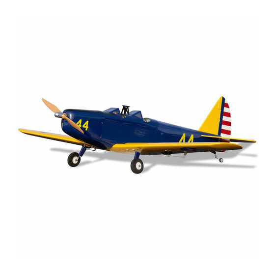
SPECIFICATIONS
Wingspan:
41.5 in [1055mm]
Wing Area:
270 sq in
2
[17.4dm
]
Weight:
23-29 oz
[650-820g]
WARRANTY
Great Planes
®
Model Manufacturing Co. guarantees this kit to
be free from defects in both material and workmanship at the
date of purchase. This warranty does not cover any component
parts damaged by use or modification. In no case shall Great
Planes' liability exceed the original cost of the purchased kit.
Further, Great Planes reserves the right to change or modify this
warranty without notice.
In that Great Planes has no control over the final assembly or
material used for final assembly, no liability shall be assumed nor
accepted for any damage resulting from the use by the user of
the final user-assembled product. By the act of using the
user-assembled product, the user accepts all resulting liability.
If the buyer is not prepared to accept the liability associated
with the use of this product, the buyer is advised to return
READ THROUGH THIS MANUAL BEFORE STARTING CONSTRUCTION. IT CONTAINS IMPORTANT
INSTRUCTIONS AND WARNINGS CONCERNING THE ASSEMBLY AND USE OF THIS MODEL.
Entire Contents © Copyright 2009
INSTRUCTION MANUAL
2
Wing
12.3-15.5 oz/ft
2
Loading:
[38-47g/dm
]
Length:
31.5 in [800mm]
Motor:
ElectriFly
™
RimFire
(28-30-950) Brushless
this kit immediately in new and unused condition to the
place of purchase.
To make a warranty claim send the defective part or item to
Hobby Services at the address below:
Include a letter stating your name, return shipping address, as
much contact information as possible (daytime telephone
number, fax number, e-mail address), a detailed description of
the problem and a photocopy of the purchase receipt. Upon
receipt of the package the problem will be evaluated as quickly
as possible.
Propeller:
Great Planes
Slo-Flyer Electric Prop
ESC:
ElectriFly
Battery:
11.1V, 1250-1600mAh LiPo
™
400
Radio:
4-Channel (minimum) with Micro
Receiver, three Micro Servos
Hobby Services
3002 N. Apollo Dr. Suite 1
Champaign IL 61822 USA
Champaign, Illinois
(217) 398-8970, Ext 5
airsupport@greatplanes.com
®
10x4.5
™
SS-25
GPMA1149 Mnl
Advertisement
Table of Contents

Subscribe to Our Youtube Channel
Related Manuals for GREAT PLANES fairchild PT-19


Summary of Contents for GREAT PLANES fairchild PT-19
-
Page 1: Instruction Manual
3002 N. Apollo Dr. Suite 1 Champaign IL 61822 USA In that Great Planes has no control over the final assembly or material used for final assembly, no liability shall be assumed nor Include a letter stating your name, return shipping address, as... -
Page 2: Table Of Contents
KIT CONTENTS ....... . 5 PT-19 EP visit the Great Planes web site at www.greatplanes. -
Page 3: Lithium Battery Handling And Usage
❍ Great Planes RimFire ™ 400 (28-30-950) Brushless cause bodily harm! Outrunner Motor (GPMG4560) ● ONLY use a LiPo approved charger. ❍ Great Planes Silver Series 25A Brushless ESC 5V/2A ● NEVER charge in excess of 4.20V per cell. BEC (GPMM1820) -
Page 4: Battery Pack And Accessories
❍ 2 oz. [57g] spray CA activator (GPMR6035) The following battery packs are recommended. ❍ 4 oz. [113g] aerosol CA activator (GPMR634) ❍ Great Planes LiPo 1600mAh BP Series 11.1V 20C ❍ Epoxy brushes (6, GPMR8060) Discharge w/ Balance (GPMP0719) ❍... -
Page 5: Kit Inspection
Kit Contents list. fi lm. Should repairs ever be required, MonoKote can be patched with additional MonoKote purchased separately. Great Planes Product Support MonoKote is packaged in six-foot rolls, but some hobby 3002 N Apollo Drive, Suite 1 shops also sell it by the foot. -
Page 6: Ordering Replacement Parts
List that follows. The fastest, most economical service can be provided by your hobby dealer or mail-order company. To locate a hobby dealer, visit the Great Planes web site at www.greatplanes.com. Select “Where to Buy” in the menu across the top of the page and follow the instructions provided to locate a U.S., Canadian or International dealer. -
Page 7: Install The Aileron Servo
so that one overlies the other. You now have a single 5mm thick wing joiner. ❏ 6. After the epoxy cures, remove the clamps and the tape from the wing. Turn the wing over. Apply some 6-minute epoxy to the wing bolt plate and glue it to the bottom side of ❏... - Page 8 ❏ 6. Use a #55 [1.3mm] drill to enlarge the two servo arm holes that are 1/2" [12.7mm] from the center of the output ❏ 3. Remove the servo arm from the servo. Install your aileron shaft. These are the outermost holes of the standard servo servo so that the output shaft is oriented forward.
-
Page 9: Install The Main Landing Gear
Install the Main Landing Gear ❏ ❏ 1. Install a wheel onto the main landing gear axle. Fit a plastic wheel collar onto the end of the axle. Apply a drop of medium CA to the end of the axle and wheel collar to ❏... -
Page 10: Install The Tail
INSTALL THE TAIL Install the Horizontal Stabilizer & Elevators ❏ 1. Temporarily fi t the wing to the fuselage using two 3mm x 25mm machine screws and two 3mm washers. ❏ 5. Align the trailing edge (TE) of the stabilizer left to right so that distance A = A1. -
Page 11: Install The Vertical Stabilizer, Rudder And Tailwheel
❏ 11. Wick about 4-5 drops of thin CA into each leg of the elevator joiner wire. Do this for both elevator halves. Clean up any excess CA with a paper towel. ❏ 8. Prepare four hinges using T-pins as shown. Insert the T-pin through the center of each hinge. -
Page 12: Install The Elevator And Rudder Servos
❏ 8. Tighten the set screw on the wheel collar for the tailwheel wire and apply a few drops of thin CA into the tailwheel guide wire. ❏ 5. Fit the tailwheel assembly to the rudder by sliding the guide wire into the pre-drilled hole in the rudder. Do not glue INSTALL THE ELEVATOR it in place at this time. - Page 13 ❏ 3. Epoxy the servo mounting plate to the servo tray. Screw the elevator servo in position so that the output shaft of the servo is oriented forward. ❏ 5. Fit the Z-bend side of the elevator pushrod into the outer pushrod hole of the control horn.
- Page 14 ❏ ❏ 7. With your servo centered, fi t the standard size servo 10. Fit the remaining control horn to the pushrod. Align arm to your servo so that the servo arm is 90° to the pushrod. the horn over the rudder hinge line and vertically. Drill the Use a #55 [1.3mm] drill to enlarge the outermost hole in the rudder using a 5/64"...
-
Page 15: Install The Motor, Esc, Receiver, & Battery
INSTALL THE MOTOR, ESC, RECEIVER, & BATTERY ❏ ❏ 4. Cut a 1" [25.4mm] length of adhesive backed hook- 1. Remove the three backplate screws, the brass collar and-loop material and apply the loop side (fuzzy side) to the set screw, and apply thread locking compound to the screw back of your ESC. -
Page 16: Finish The Model
❏ ❏ 7. Prepare the surface and attach the remaining adhesive 9. Note: DO NOT accomplish this step with the propeller backed hook-and-loop material (hook side) to the battery tray installed! Turn on your transmitter. If you have a Futaba radio in the location shown. - Page 17 ❏ ❏ 2. Connect the aileron servo lead to the receiver. If you 5. Using a 1/16" [1.6mm] drill bit, drill two holes per side are using a 2.4GHz radio, arrange your receiver’s antennas of the cowl that are 1/2" [12.7mm] forward of the rear edge of as directed by the radio manufacturer.
-
Page 18: Pilot Installation (Optional)
❏ 8. Using some scrap balsa, cut four short strips to make ❏ 11. Cut out the instrument panel decals. Trim them to fi t fl anges to help join the left and right pieces. Glue two fl anges and apply them to both cockpits now. to one half using thin CA. -
Page 19: Apply The Decals
GET THE MODEL READY TO FLY Check the Control Directions Warning: Once the battery is connected to the ESC, stay clear of the propeller! Always stay behind the propeller! ❏ 1. Turn on the transmitter, center the trims, and move the throttle stick all the way down. -
Page 20: Balance The Model (C.g.)
3. With all parts of the model installed (ready to fl y) and a AILERONS [10mm] [10mm] [6mm] [6mm] battery pack in place (do not connect it), use a Great Planes 23 deg 23 deg 15 deg 15 deg C.G. Machine, or place your fi ngers on the marks you made... -
Page 21: Balance The Model Laterally
Balance Propellers in the battery compartment. ❏ 6. If additional weight is required, use Great Planes (GPMQ4485) “stick-on” lead. A good place to add stick- on nose weight is to the fi rewall (don’t attach weight to the cowl—it is not intended to support weight). Begin by placing increasing amounts of weight on the top of the fuse over the fi... -
Page 22: Motor Safety Precautions
Radio Control MOTOR SAFETY PRECAUTIONS 1) I will have completed a successful radio equipment ground Failure to follow these safety precautions may result check before the fi rst fl ight of a new or repaired model. in severe injury to yourself and others. 2) I will not fl... -
Page 23: Flying
❏ 9. Pull / push on each of the pushrods and check to see Takeoff that the adjustable pushrod connectors do not slip. ❏ 10. Check the servo arms for secure attachment and The goals of your fi rst fl ight should be to trim the airplane make sure that the arm screws are in place and are tight. -
Page 24: Landing
but to hold the turn you’ll need rudder and a little opposite aileron to keep your bank angle. Try transitioning from left to right and making turns into the wind and with the wind. Line yourself up for a few practice landing approaches. Slow down and line yourself up while practicing your descent.
Need help?
Do you have a question about the fairchild PT-19 and is the answer not in the manual?
Questions and answers