Table of Contents
Advertisement
Quick Links
Download this manual
See also:
Instruction Manual
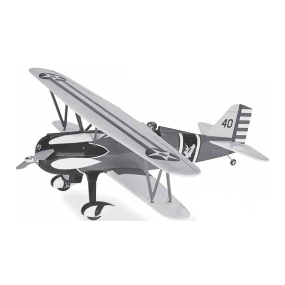
CURTISS P-6E HAWK
SPECIFICATIONS
Wingspan: 43.5 in [1105mm]
Length: 34 in [865mm]
Weight: 3.75– 4.5 lb [1700 – 2040 g]
WARRANTY
Great Planes
®
Model Manufacturing Co. guarantees this kit to
be free from defects in both material and workmanship at the
date of purchase. This warranty does not cover any component
parts damaged by use or modification. In no case shall Great
Planes' liability exceed the original cost of the purchased kit.
Further, Great Planes reserves the right to change or modify this
warranty without notice.
In that Great Planes has no control over the final assembly or
material used for final assembly, no liability shall be assumed nor
accepted for any damage resulting from the use by the user of
the final user-assembled product. By the act of using the
user-assembled product, the user accepts all resulting liability.
If the buyer is not prepared to accept the liability associated
with the use of this product, the buyer is advised to return
READ THROUGH THIS MANUAL BEFORE STARTING CONSTRUCTION. IT CONTAINS IMPORTANT
INSTRUCTIONS AND WARNINGS CONCERNING THE ASSEMBLY AND USE OF THIS MODEL.
®
Entire Contents © 2014 Hobbico,
Inc. All rights reserved.
INSTRUCTION MANUAL
2
Wing Area: 352 in
Wing Loading: 25– 29 oz/ft
[76– 88 g /dm
this kit immediately in new and unused condition to the
place of purchase.
To make a warranty claim send the defective part or item to
Hobby Services at the address below:
Include a letter stating your name, return shipping address, as
much contact information as possible (daytime telephone
number, fax number, e-mail address), a detailed description of
the problem and a photocopy of the purchase receipt. Upon
receipt of the package the problem will be evaluated as quickly
as possible.
Radio: 4 channel radio (minimum)
2
[22.7 dm
]
Electric
2
Power:
2
]
Hobby Services
3002 N. Apollo Dr. Suite 1
Champaign IL 61822 USA
Champaign, Illinois
(217) 398-8970, Ext 5
airsupport@greatplanes.com
RimFire™ .32, (42-50-800)
Outrunner Brushless
GPMA1164
Advertisement
Table of Contents

Subscribe to Our Youtube Channel
Related Manuals for GREAT PLANES Curtiss P-6E Hawk


Summary of Contents for GREAT PLANES Curtiss P-6E Hawk
-
Page 1: Instruction Manual
3002 N. Apollo Dr. Suite 1 Champaign IL 61822 USA In that Great Planes has no control over the final assembly or material used for final assembly, no liability shall be assumed nor Include a letter stating your name, return shipping address, as... -
Page 2: Table Of Contents
AMA chartered clubs across the country. Contact the AMA at INTRODUCTION the address or toll-free phone number below: The Curtiss P-6E Hawk is an iconic airplane loved by aviation Academy of Model Aeronautics enthusiasts everywhere. The attention to detail in this airplane,... -
Page 3: Decisions You Must Make
6. You must check the operation of the model before every fl ight to insure that all equipment is operating and that the The Curtiss P-6E Hawk EP ARF comes with a mounting box model has remained structurally sound. Be sure to check for the Great Planes RimFire brushless out-runner motor. -
Page 4: Optional Supplies And Tools
ORDERING REPLACEMENT PARTS Here is a list of optional tools mentioned in the manual that Replacement parts for the Great Planes Curtiss P-6E Hawk will help you build the Curtiss P-6E Hawk EP. are available using the order numbers in the Replacement Parts List that follows. -
Page 5: Kit Contents
KIT CONTENTS Lower Wing Upper Wing Fuselage Hatch Fin and Rudder Stab and Elevator "N" Struts Brackets Cabane Struts Cowl Wheel Pants Turtle Deck Fairing Landing Gear Wheels Tail Wheel Wire and Tail Wheel Landing Gear Fairings Windshield PREPARATIONS 1. If you have not done so already, remove the major parts of the kit from the box and inspect for damage. - Page 6 ❏ ❏ 7. Place your servo onto the servo hatch, positioning it so that the control horn is centered in the opening in the hatch. Glue two 9/32" x 3/8" x 3/8" [7 x 10 x 10mm] wood blocks to the hatch, positioning the servo between the wood mounting blocks with 5 minute epoxy.
- Page 7 ❏ ❏ 11. Thread a nylon clevis, 20 turns, onto a 6" [152mm] wire pushrod. ❏ ❏ 12. Slide a silicone clevis retainer over the clevis and install the clevis into the outer hole in the aileron control horn. With the aileron servo and the aileron centered, mark the aileron pushrod where it crosses the aileron servo arm.
-
Page 8: Assemble The Fuselage
Install the Main Landing Gear ❏ 14. When installing the servo in the left half of the wing you may wish to have the extension exit the wing through the ❏ same hole as the right aileron. This may be helpful in hiding 1. -
Page 9: Install The Wings, Cabanes & Struts
❏ 4. Test fi t the landing gear cuff to the landing gear. When you are satisfi ed with the fi t of the cuff over the landing gear, glue the cuff in place to the wood parts. You will complete the installation of the wheels and wheel pants in a later step. - Page 10 ❏ 2. Install the lower wing to the fuselage with two ¼-20 x 2" [51mm] nylon wing bolts. ❏ 5. Install the struts to the bottom wing with 4-40 x 5/16" [3 x 8mm] machine screws, #4 lock washers and fl at washers. ❏...
-
Page 11: Install The Tail Assembly
which cabane goes on each side of the fuselage. On the marks you made in the fuselage, drill a 3/32" [2.5mm] hole through the fuselage sides. Insert and remove a 1/8" x 3/8" washer head screw into each of the four holes. Apply a drop of thin CA into each of the holes to harden the threads. - Page 12 ❏ 4. Look closely at the leading edge of the elevator. You ❏ 3. Using a sharp hobby knife, cut the covering inside the will notice on one side there is a plywood plate. This is the lines you traced onto the parts. When cutting the covering bottom of the stabilizer and elevator.
-
Page 13: Install The Elevator, Rudder Servos And Receiver
horn onto the elevator with the holes centered over the hinge line. Mark the location of the screw holes. Drill a 3/32" [2.5mm] hole through the elevator on each of the marks. Secure the horn to the elevator with two 1/16" x ½" machine screws and the nylon back plate. -
Page 14: Install The Motor, Esc And Cowl
❏ tray as shown. Plug the elevator and rudder servos into the 6. Remove three of the arms from a four arm servo horn. appropriate channels on your receiver. Drill the outer hole of the arm with a 5/64" [2mm] drill. Place the elevator servo arm outer hole in line with the pushrod wire. - Page 15 ❏ 5. Position the cowl over the motor, centering the motor with the hole in the front of the cowl. Be sure the motor prop fl ange extends beyond the front of the cowl to allow for clearance for the propeller. ❏...
-
Page 16: Install The Wheels And Wheel Pants
Install the Wheels and Wheel Pants ❏ ❏ 3. Slide the right side wheel pant over the wheel. Secure the wheel pant to the landing gear with two 2-56 x ½" [13mm] screws, #2 lock washers and #2 fl at washers. Repeat this for the remaining wheel pant. -
Page 17: Final Details
Final Details ❏ 1. Glue the turtle deck in place to the top of the fuselage. A white aliphatic glue such as Formula 500 canopy glue works well for this. Tape the turtle deck to the fuselage while the ❏ 4. -
Page 18: Get The Model Ready To Fly
❏ 3. Use a piece of soft balsa or something similar to squeegee remaining water from under the decal. Apply the rest of the decals the same way GET THE MODEL READY TO FLY Note: If you have not re-installed the wings, install them now. Check the Control Directions ❏... -
Page 19: Set The Control Throws
fl ights. If, after you have become accustomed to the way smoothness and stability, but the model may then require Curtiss P-6E Hawk EP fl ies, you would like to change the more speed for takeoff and make it more diffi cult to slow throws to suit your taste, that is fi... -
Page 20: Balance The Model Laterally
If additional weight pack or a defective cell, or a damaged receiver crystal from is required, use Great Planes (GPMQ4485) “stick-on” lead. A a previous crash. The problem may be the location of the good place to add stick-on nose weight is to the motor box antenna. -
Page 21: Ama Safety Code Excerpts
AMA SAFETY CODE EXCERPTS CHECK LIST Read and abide by the following excerpts from the Academy During the last few moments of preparation your mind may of Model Aeronautics Safety Code. For the complete Safety be elsewhere anticipating the excitement of the fi rst fl ight. Code refer to Model Aviation magazine, the AMA web site or Because of this, you may be more likely to overlook certain the Code that came with your AMA license. -
Page 22: Flying
CAUTION (THIS APPLIES TO ALL R/C AIRPLANES): If, Take it easy with the Curtiss P-6E Hawk for the fi rst fl ight, while fl ying, you notice an alarming or unusual sound such gradually getting acquainted with it as you gain confi... - Page 23 importantly so you do not surprise yourself by impulsively attempting a maneuver and suddenly fi nding that you’ve run out of time, altitude or airspeed. Every maneuver should be deliberate, not impulsive. For example, if you’re going to do a loop, check your altitude, mind the wind direction (anticipating rudder corrections that will be required to maintain heading), remember to throttle back at the top, and make certain you...
- Page 24 ® Entire Contents © 2014 Hobbico, Inc. All rights reserved. GPMA1164...
Need help?
Do you have a question about the Curtiss P-6E Hawk and is the answer not in the manual?
Questions and answers