Table of Contents
Advertisement
Quick Links
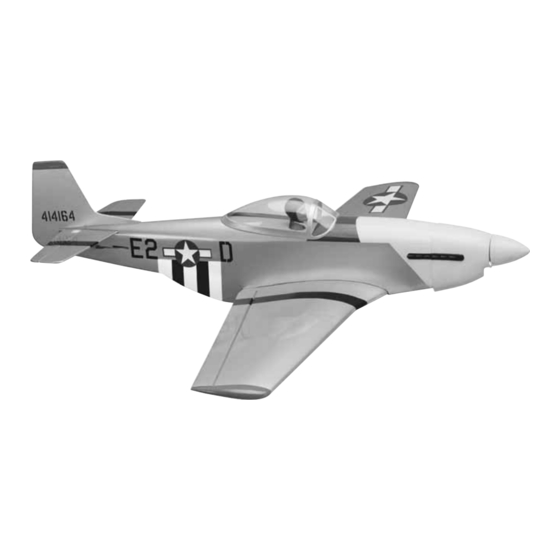
Wingspan: 38-1/2 in [975mm]
Wing Area: 264 sq in [17dm
Weight: 2.5 – 3 lb [1130 –1360g]
Wing Loading: 22 – 26 oz/sq ft [70 – 80g/dm
Length: 34 in [865mm]
Radio: 3-channel
Engine: .15 – .25 cu in [2.5 – 4cc] two-stroke,
.30 cu in [5cc] four-stroke
Great Planes
Model Manufacturing Co. guarantees this kit to be free from defects in both material and workmanship at the date of purchase. This warranty
®
does not cover any component parts damaged by use or modification. In no case shall Great Planes' liability exceed the original cost of the purchased kit.
Further, Great Planes reserves the right to change or modify this warranty without notice.
In that Great Planes has no control over the final assembly or material used for final assembly, no liability shall be assumed nor accepted for any damage resulting
from the use by the user of the final user-assembled product. By the act of using the user-assembled product, the user accepts all resulting liability.
If the buyer is not prepared to accept the liability associated with the use of this product, the buyer is advised to return this kit immediately in new and
unused condition to the place of purchase.
To make a warranty claim send the defective part or item to Hobby Services at the address below:
Include a letter stating your name, return shipping address, as much contact information as possible (daytime telephone number, fax number, e-mail address), a
detailed description of the problem and a photocopy of the purchase receipt. Upon receipt of the package the problem will be evaluated as quickly as possible.
READ THROUGH THIS MANUAL BEFORE STARTING
CONSTRUCTION. IT CONTAINS IMPORTANT INSTRUCTIONS
AND WARNINGS CONCERNING THE ASSEMBLY AND
USE OF THIS MODEL.
GPMZ0287 for GPMA1475 V1.0
INSTRUCTION MANUAL
]
2
]
2
3002 N. Apollo Dr., Suite 1
WARRANTY
Hobby Services
Champaign, IL 61822
USA
Champaign, IL
(217) 398-8970, Ext. 5
airsupport@greatplanes.com
Entire Contents © Copyright 2005
Advertisement
Table of Contents

Related Manuals for GREAT PLANES COMBAT MUSTANG Combat P-51 ARF


Summary of Contents for GREAT PLANES COMBAT MUSTANG Combat P-51 ARF
- Page 1 Further, Great Planes reserves the right to change or modify this warranty without notice. In that Great Planes has no control over the final assembly or material used for final assembly, no liability shall be assumed nor accepted for any damage resulting from the use by the user of the final user-assembled product.
-
Page 2: Table Of Contents
9. WARNING: The cowl in this kit is made of fiberglass, the The Great Planes 1/12-scale Combat P-51 ARF is a great fibers of which may cause eye, skin and respiratory tract flying model suitable for sport flying or Combat Class irritation. -
Page 3: Additional Items Required
“short list” of the most important items required to way guarantee the performance of your completed build the Combat P-51 ARF. Great Planes Pro CA and ™... -
Page 4: Common Abbreviations
= millimeters ORDERING REPLACEMENT PARTS Replacement parts for the Great Planes Combat P-51 ARF are available using the order numbers in the Replacement Parts List that follows. The fastest, most economical service can be provided by your hobby dealer or mail- order company. -
Page 5: Kit Contents
If any parts are missing or are not of acceptable quality, or if you need assistance with assembly, contact Great Planes Product Support. When reporting defective or missing parts, use the part names exactly as they are written in the “... -
Page 6: Preparations
PREPARATIONS 1. If you have not done so already, remove the major parts of the kit from the box and inspect for damage. If any parts are damaged or missing, contact Product Support at the address or telephone number listed in the “Kit Contents”... - Page 7 [86mm] from the tip of the wing to the bench. The dihedral is not critical. A measurement between 3" [76mm] and 3-5/8" [92mm] is acceptable. HOW TO CUT COVERING FROM BALSA Use a soldering iron to cut the covering from the stab. The tip of the soldering iron doesn’t have to be sharp, but a fine-tip does work best.
-
Page 8: Install The Aileron Servo & Pushrods
8. Position the plywood aileron servo tray over the servo location in the center-section of the wing. Trace the outline of the tray onto the wing with a fine-tipped marker. Carefully cut the covering from the wing inside the lines you have made on the wing. -
Page 9: Install The Belly Pan
Install the Belly Pan 2. Insert the horizontal stab into the fuselage. Position the horizontal stab so that it is centered in the fuselage. The distance from each end of the horizontal stab to the fuselage should be the same distance. 1. -
Page 10: Install Elevator Pushrods & Servo
glue the horizontal stab to the fuselage by wicking thin CA into the joint. Do this on both the top and bottom of the horizontal stab. 5. Insert a hinge into each of the elevator and horizontal stab hinge slots, checking to be sure the hinge fits easily into the slot. -
Page 11: Install The Engine, Fuel Tank & Throttle Servo
3. Slide the pushrod wire into the hole in the side of the fuselage. Position a nylon control horn onto the elevator. Mark the location of the screw holes. Then drill a 5/64" [2mm] hole on the marks, drilling through the elevator. Install 5. - Page 12 2. Locate a 4-1/2" [114mm] balsa stick. Cut it as needed 4. On the side of the engine mount are reference marks. to fit in the fuselage to hold the fuel tank in position. When Align the marks that are in line with the engine mounting you have completed the installation of the fuel tank and the rails with the lines on the firewall.
-
Page 13: Install The Cowl, Prop & Spinner
Refer to this photo for steps 9-12. 3. Holding the cowl in place, drill four 1/16" [1.6mm] holes in the side of the cowl and through the plywood tab that extends from the fuselage sides. Install a 2 x 8mm washer head screw into each of the holes. -
Page 14: Finishing Touches
6. Working from the middle to the outside, use a piece of Use a Great Planes AccuThrow (or a ruler) to accurately soft balsa or something similar to squeegee remaining measure and set the control throw of each control surface water from under the decal. -
Page 15: Balance The Model (C.g.)
2. With the wing attached to the fuselage, all parts of the model installed (ready-to-fly) and an empty fuel tank, place the model upside-down on a Great Planes CG Machine, or Balance the Model (C.G.) lift it upside-down at the balance point you marked. -
Page 16: Balance The Model Laterally
™ No matter if you fly at an AMA sanctioned R/C club site or if you (TOPQ5700) in the workshop and keep a Great Planes fly somewhere on your own, you should always have your Fingertip Prop Balancer (GPMQ5000) in our flight box. -
Page 17: Engine Safety Precautions
2. I will not fly my model aircraft higher than approximately ENGINE SAFETY PRECAUTIONS 400 feet within 3 miles of an airport without notifying the airport operator. I will give right of way to, and avoid flying in the proximity of full-scale aircraft. Where necessary an observer shall be used to supervise flying to avoid having Failure to follow these safety precautions may result models fly in the proximity of full-scale aircraft. -
Page 18: Flying
6. Use thread-locking compound to secure critical CAUTION (THIS APPLIES TO ALL R/C AIRPLANES): If, fasteners such as the set screws, screws that hold while flying, you notice an alarming or unusual sound the carburetor arm (if applicable), screw-lock such as a low-pitched “buzz,” this may indicate control pushrod connectors, etc. -
Page 19: Landing
Continue to fly around, executing OTHER ITEMS AVAILABLE FROM various maneuvers and making mental notes (or having GREAT PLANES your assistant write them down) of what trim or C.G. changes may be required to fine tune the model so it flies the way you like. - Page 20 BUILDING NOTES Kit Purchased Date: _______________________ Date Construction Finished: _________________ Where Purchased:_________________________ Finished Weight: __________________________ Date Construction Started: __________________ Date of First Flight: ________________________ FLIGHT LOG...
Need help?
Do you have a question about the COMBAT MUSTANG Combat P-51 ARF and is the answer not in the manual?
Questions and answers