Table of Contents
Advertisement
Quick Links
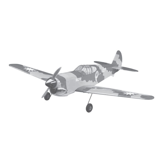
Wingspan: 39 in [985mm]
Wing Area: 242 in
2
[15.6dm
2
]
Weight: 38 – 46 oz [1080 – 1300g]
2
Wing Loading: 23 – 27 oz/ft
[69 – 84g/dm
Length: 34.5 in [875mm]
Radio:
4-channel with three to four micro servos and
standard size receiver
Engine / Motor:
.25 cu in [4cc] two-stroke engine,
RimFire
™
35-30-1450kV brushless out-runner motor
Great Planes
®
Model Manufacturing Co. guarantees this kit to be free from defects in both material and workmanship at the date of purchase.
This warranty does not cover any component parts damaged by use or modifi cation. In no case shall Great Planes' liability exceed the
original cost of the purchased kit. Further, Great Planes reserves the right to change or modify this warranty without notice.
In that Great Planes has no control over the fi nal assembly or material used for fi nal assembly, no liability shall be assumed nor accepted
for any damage resulting from the use by the user of the fi nal user-assembled product. By the act of using the user-assembled product,
the user accepts all resulting liability.
If the buyer is not prepared to accept the liability associated with the use of this product, the buyer is advised to return this kit
immediately in new and unused condition to the place of purchase.
To make a warranty claim send the defective part or item to Hobby Services at the address below:
Include a letter stating your name, return shipping address, as much contact information as possible (daytime telephone number, fax
number, e-mail address), a detailed description of the problem and a photocopy of the purchase receipt. Upon receipt of the package
the problem will be evaluated as quickly as possible.
READ THROUGH THIS MANUAL BEFORE
STARTING CONSTRUCTION. IT CONTAINS
IMPORTANT INSTRUCTIONS AND WARNINGS
CONCERNING THE ASSEMBLY AND USE OF
THIS MODEL.
Entire Contents © Copyright 2007
INSTRUCTION MANUAL
2
]
WARRANTY
Hobby Services
3002 N. Apollo Dr., Suite 1
Champaign, IL 61822 USA
Champaign, Illinois
(217) 398-8970, Ext 5
airsupport@greatplanes.com
GPMZ1472 for GPMA1472 V1.0
Advertisement
Table of Contents

Related Manuals for GREAT PLANES P-40 Warhawk


Summary of Contents for GREAT PLANES P-40 Warhawk
-
Page 1: Instruction Manual
Further, Great Planes reserves the right to change or modify this warranty without notice. In that Great Planes has no control over the fi nal assembly or material used for fi nal assembly, no liability shall be assumed nor accepted for any damage resulting from the use by the user of the fi... -
Page 2: Table Of Contents
For the latest technical updates or manual corrections to the ADDITIONAL ITEMS REQUIRED ........4 P-40 Warhawk ARF visit the Great Planes web site at www. Required Hardware & Accessories ......4 greatplanes.com. Open the “Airplanes” link, then select the Adhesives &... -
Page 3: Safety Precautions
1. Your P-40 Warhawk ARF should not be considered a toy, and no representations are expressed or implied as to the but rather a sophisticated, working model that functions very performance or safety of your completed model. -
Page 4: Batteries & Charger
Optional Supplies & Tools Propeller Here is a list of optional tools that will help you build the P-40 If using the O.S. .25 FX glow engine or the Great Planes Warhawk ARF: 35-30-1450kV RimFire out-runner motor, we suggest using a 9"... -
Page 5: Building Stand
Top Flite MonoKote heat gun (TOPR2000) ❏ Hobbico pin vise 1/16" collet w/6 bits (HCAR0696) Replacement parts for the Great Planes P-40 Warhawk ARF ❏ Hobbico 7-piece ball tip hex L-wrench metric (HCAR0521) are available using the order numbers in the Replacement ❏... -
Page 6: Common Abbreviations
COMMON ABBREVIATIONS METRIC CONVERSIONS Fuse = Fuselage " = 25.4mm (conversion factor) Stab = Horizontal Stabilizer 1/64" = .4mm 3/4" = 19.0mm Fin = Vertical Fin 1/32" = .8mm 1" = 25.4mm LE = Leading Edge 1/16" = 1.6mm 2" = 50.8mm 3/32"... -
Page 7: Kit Inspection
If any parts are missing or are not of acceptable quality, or if you need assistance with assembly, contact Product Support. When reporting defective or missing parts, use the part names exactly as they are written in the Kit Contents list. Great Planes Product Support: 3002 N Apollo Drive, Suite 1 Champaign, IL 61822 Telephone: (217) 398-8970, ext. -
Page 8: Preparations
PREPARATIONS ❏ 1. If you have not done so already, remove the major parts of the kit from the box and inspect for damage. If any parts are damaged or missing, contact Product Support at the address or telephone number listed in the “Kit Inspection” section on page 7. - Page 9 ❏ ❏ 6. Trim the covering that overlaps onto the root ribs of 9. Align the wing bolt plate over the holes on the each wing panel. Test fi t the joiner into both wing halves. The underside of the wing. There is a shallow perforation on the joiner should fi...
-
Page 10: Install The Aileron Servos & Pushrods
Install the Aileron Servo & Pushrods ❏ 4. Screw the aileron torque rod horns onto the threaded ends of the torque rods fl ush with the ends of the rods. Position the horns to point forward. ❏ 1. Install the rubber grommets and eyelets that were included with the servo. -
Page 11: Build The Fuse
clevises to the torque rod horns and install the 90° bend in the wires into the outer holes of the servo arms. Secure the wires with two nylon FasLinks. Confi rm that the ailerons are both in the neutral position with the servo arm perpendicular to the servo case. - Page 12 beneath the lines you drew (leave the covering on the TE of the fi n in place). Use epoxy to glue the fi n in position. ❏ 8. Insert a hinge half way into each hinge slot in the stab and keep them centered with a pin.
-
Page 13: Install The Elevator & Rudder Pushrods & Servos
control horn onto the underside of the left elevator half and position the holes over the hinge line at a slight inward angle Install the Elevator & Rudder matching the angle of the pushrod. When satisfi ed, mark Pushrods & Servos the locations for the control horn mounting screws. -
Page 14: Glow Engine, Fuel Tank & Radio Installation
Glow Engine, Fuel Tank & Radio Installation The P-40 Warhawk ARF is designed to be fl own with a .25 glow engine or an out-runner brushless motor. If you plan to install a brushless motor, skip this section as it only contains information relevant to installing a glow engine. - Page 15 reach the back of the tank but not touch. The clunk must be able to move freely inside the tank when assembled. Adjust the length of the fuel tubing accordingly. If you wish to use the fi ll line to drain the tank, attach a length of fuel tubing and an additional fuel clunk (not included) to the fi...
- Page 16 use a 3mm tap and drill set to create threads in the four mounting rubber that fi ts your receiver battery pack and sandwich holes. Attach the engine to the mount using four 3mm x 20mm it between the pack and the receiver tray. With the pack SHCS, four 3mm lock washers, and four 3mm fl...
- Page 17 ❏ 15. Install the .039" x 13-3/4" [1mm x 350mm] throttle pushrod with Z-bend into the outer pushrod tube and connect the Z-bend to your engine throttle arm (you may ❏ 13. Drill a 1/8" [3.2mm] hole through the fi rewall inline need to remove the arm from the carburetor to do this).
-
Page 18: Out-Runner Motor, Battery & Radio Installation
to length and connect the vent line to the muffl er and the carb line to the fuel inlet on the needle valve. A plastic fi ll line plug has been provided to plug the fi ll line if you installed one. Out-runner Motor, Battery &... - Page 19 ❏ 7. Cut a 1-1/2" [38mm] piece from the included 1/4" [6mm] ❏ tri-stock. Glue the piece fl ush with the top edge of the fuel 10. Glue the brushless radio tray to the stringers in the tank opening as shown. This will provide a larger mounting location shown.
- Page 20 MAKE BATTERY CONNECTOR ADAPTERS If the Great Planes 4mm male to 3.5mm female bullet connector adapters are not available, or you would like to make your own, the assembly procedure and order numbers for the individual parts are provided below.
-
Page 21: Finish The Model
FINISH THE MODEL Install the Cowl The cowl installation is shown on the brushless motor power system. Installing the cowl over a glow engine is the same. However, in addition to cutting a cooling hole for the engine head, you will also need to make a hole for glow plug access, a hole to access the needle valve, and a cutout for the muffl... -
Page 22: Final Assembly
you reach the receiver with the tube, feed as much of the antenna into the tube as possible, then pull the tube with the antenna inside of it out through the hole. ❏ 2. If you have not done so already, connect the elevator and rudder servos to the receiver. -
Page 23: Optional Landing Gear
The included landing gear is recommended for paved runways only. If you plan to fl y the P-40 Warhawk ARF in combat competition, we suggest omitting the gear for reduced weight and increased maneuverability. -
Page 24: Apply The Decals
edges of the tail skid. The washer will prevent the tail skid from rubbing away when fl ying from a paved runway. ❏ 3. Remove the wheels and wheel collars and grind fl at spots on the axles where the set screws made marks from ®... -
Page 25: Get The Model Ready To Fly
fi rst fl ights. If, after you have become accustomed to the way the Combat P-40 Warhawk ARF fl ies, you would like to change the throws to suit your taste, that is fi ne. However, too much control throw could make the model diffi... -
Page 26: Balance The Model Laterally
2. With the wing attached to the fuse, all parts of the model installed (ready to fl y) and an empty fuel tank, place Charge the Batteries the model upside-down on a Great Planes CG Machine, or lift it upside-down at the balance point you marked. ❏... -
Page 27: Balance The Propellers
We use a Top Flite Precision Magnetic Prop Balancer (TOPQ5700) in the workshop and keep a Great Planes Keep these items away from the prop: loose clothing, shirt Fingertip Prop Balancer (GPMQ5000) in our fl ight box. -
Page 28: Ama Safety Code (Excerpts)
• NEVER charge at currents greater than 1C. 3) At all fl ying sites a straight or curved line(s) must be • ALWAYS set charger’s output volts to match battery volts. established in front of which all fl ying takes place with the •... -
Page 29: Flying
At this moment it is likely that you will need to apply more right The P-40 Warhawk ARF is a great-fl ying model that fl ies rudder to counteract engine torque. Be smooth on the elevator smoothly and predictably. -
Page 30: Flight
While full throttle is usually desirable for takeoff, most models fl y more smoothly at reduced speeds. Take it easy with the P-40 Warhawk ARF for the fi rst few fl ights, gradually getting acquainted with it as you gain confi... - Page 31 Great Planes ElectriFly ™ 35-30-1450 RimFire ™ ElectriFly by Great Planes 3200mAh Power Series LiPo Out-runner Brushless Motor Battery with Balance Connector Ideal for scale aircraft, bigger sport aerobats, 3D planes, and • Highly effi cient and virtually maintenance-free. Bearings larger electric models, the Power Series 3200mAh LiPo pack are double-shielded and permanently lubricated.
- Page 32 BUILDING NOTES Kit Purchased Date: ___________________________ Date Construction Finished: _______________________ Where Purchased: ____________________________ Finished Weight: _______________________________ Date Construction Started: _____________________ Date of First Flight: ______________________________ FLIGHT LOG...
Need help?
Do you have a question about the P-40 Warhawk and is the answer not in the manual?
Questions and answers