Table of Contents
Advertisement
Quick Links
I N S T R U C T I O N M A N U A L
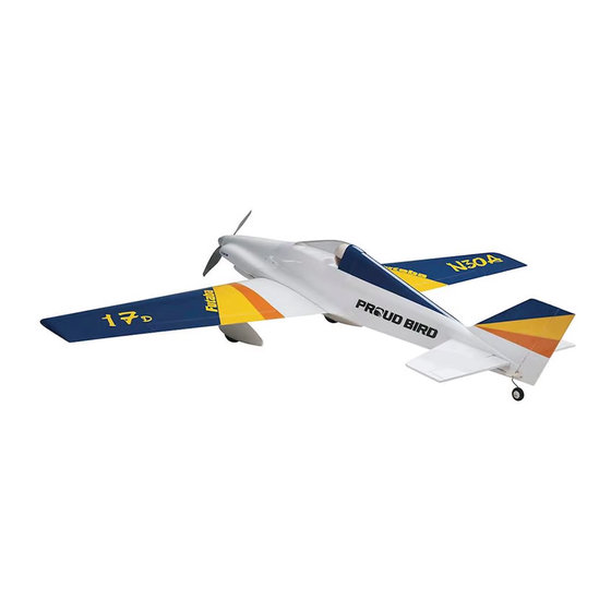
Wingspan: 51-15/16 in [1319 mm]
Wing Area: 388 in
Wing Loading: 18−21 oz/ft
WARRANTY
Great Planes
®
Model Manufacturing Co. guarantees this kit to
be free from defects in both material and workmanship at the
date of purchase. This warranty does not cover any component
parts damaged by use or modification. In no case shall Great
Planes' liability exceed the original cost of the purchased kit.
Further, Great Planes reserves the right to change or modify this
warranty without notice.
In that Great Planes has no control over the final assembly or
material used for final assembly, no liability shall be assumed nor
accepted for any damage resulting from the use by the user of
the final user-assembled product. By the act of using the
user-assembled product, the user accepts all resulting liability.
If the buyer is not prepared to accept the liability associated
with the use of this product, the buyer is advised to return
READ THROUGH THIS MANUAL BEFORE STARTING CONSTRUCTION. IT CONTAINS IMPORTANT
INSTRUCTIONS AND WARNINGS CONCERNING THE ASSEMBLY AND USE OF THIS MODEL.
®
Entire Contents © 2012 Hobbico,
Inc. All rights reserved.
Weight: 3− 3.5 lb [1360 −1590 g]
2
2
[25 dm
]
Length: 40 in [1015 mm]
2
2
[55− 64 g /dm
]
Radio: 4+ channels
this kit immediately in new and unused condition to the
place of purchase.
To make a warranty claim send the defective part or item to
Hobby Services at the address below:
Include a letter stating your name, return shipping address, as
much contact information as possible (daytime telephone
number, fax number, e-mail address), a detailed description of
the problem and a photocopy of the purchase receipt. Upon
receipt of the package the problem will be evaluated as quickly
as possible.
Champaign, Illinois
E-mail: airsupport@greatplanes.com
SPECIFICATIONS
Electric
1200 kV Outrunner
Power:
Brushless Motor
Hobby Services
3002 N. Apollo Dr. Suite 1
Champaign IL 61822 USA
(217) 398-8970
™
GPMA1260 Mnl
Advertisement
Table of Contents

Subscribe to Our Youtube Channel
Related Manuals for GREAT PLANES Proud Bird


Summary of Contents for GREAT PLANES Proud Bird
- Page 1 3002 N. Apollo Dr. Suite 1 Champaign IL 61822 USA In that Great Planes has no control over the final assembly or material used for final assembly, no liability shall be assumed nor Include a letter stating your name, return shipping address, as...
-
Page 2: Table Of Contents
Although the Proud Bird was made for racing, it makes a great FOLLOW THESE IMPORTANT SAFETY PRECAUTIONS sport fl ier as well. The Proud Bird can be fl own with a .15 size brushless motor and a 3S battery which will give you longer 1. -
Page 3: Decisions You Must Make
35-45-1200 motor. A 60A minimum ESC is also required. We recommend the Castle Creations Ice Lite 75A ESC. If using This is a partial list of items required to fi nish the Proud Bird the recommended ESC, you will also need to purchase a male that may require planning or decision making before starting Deans Ultra connector. -
Page 4: Adhesives And Building Supplies
❍ Epoxy brushes 6, (GPMR8060) get another view of the same parts. ❍ Mixing sticks (GPMR8055) ● The Proud Bird is factory-covered with Top Flite MonoKote ❍ Mixing cups (GPMR8056) fi lm. Should repairs ever be required, MonoKote can be ❍... -
Page 5: Kit Inspection
Spinner provided by your hobby dealer or mail-order company. GPMA4308 Decals To locate a hobby dealer, visit the Great Planes web site at GPMA4309 Plastic Parts Set www.greatplanes.com. Select “Where to Buy” in the menu across the top of the page and follow the instructions provided to locate a U.S., Canadian or International dealer. -
Page 6: Preparations
PREPARATIONS ❏ 1. If you have not done so already, remove the major parts of the kit from the box and inspect for damage. If any parts are damaged or missing, contact Product Support at the address or telephone number listed in the “Kit Inspection” section on page 5. - Page 7 You can tape the wing panels together while the epoxy hardens. The panels can also be held together with spring clamps at the root tab. Slide the 4x30mm wing bolts through the wing bolt holes and wrap rubber bands around them to draw the aft end of the panels together.
- Page 8 HOW TO CUT COVERING FROM BALSA Use a soldering iron to cut the covering from the area beneath the wing bolt plate. The tip of the soldering iron doesn’t have to be sharp, but a fi ne tip does work best. Allow the iron to heat fully.
- Page 9 it and rotate it 90 degrees and re-install it. Repeat this until you fi nd which way the servo arm fi ts best onto the servo. 5/64" [2mm] Cut Off Unused Arms 17/32" [13.5mm] Make note of its orientation, remove it, and cut off the two unused arms as shown in the picture.
-
Page 10: Assemble The Tail Section
Assemble the Tail Section FasLink 1/4" [6.4 mm] ❏ 1. Temporarily mount the wing onto the fuselage using two 4x30mm screws and two 4mm fl at washers. Servo Arm Pushrod Wire ❏ 16. Use tape or small spring clamps to hold the ailerons in the neutral position. - Page 11 ❏ 5. Hinge the elevator halves onto the stabilizer just as you did with the ailerons. Ensure that the elevators are equally spaced between the stab ends. The elevators should both be centered. Pull on elevators to be sure they are securely attached. ❏...
- Page 12 ❏ 7. The tail wheel is provided to you pre-assembled from the factory. If you choose to remove the wheel to reduce drag the axle can be bent vertically to act as a tail skid. ❏ 9. Hold the rudder up against the rudder hinge line on the fuselage.
- Page 13 ❏ 11. Prepare three CA hinges with T-pins and insert them into the rudder (we recommend test fi tting the rudder and tail wheel wire onto the fuselage without glue before completing this step). Clean the section of the tail wheel wire that fi ts into the rudder with denatured alcohol.
- Page 14 FasLink 1/4" [6.4 mm] Servo Arm Pushrod Wire Remove the pushrod from the plane. Bend the pushrod 90 degrees at your mark and cut off the excess pushrod 1/4" [6.4mm] beyond the bend. Enlarge the inner hole of the pushrod to 5/64"...
-
Page 15: Install The Power System
Install the Power System ❏ ❏ 1. The Proud Bird includes eight plywood motor spacers 4. Drill 5/32" [4mm] at the marks that match the motor to accommodate different length motors. The recommended mounting hole pattern of your motor. We suggest starting with O.S. - Page 16 ❏ 8. Use a piece of self-adhesive hook and loop material or ❏ 6. The recommended O.S. motor includes 3mm female bullet make a strap from non-adhesive hook and loop material to connectors which must be soldered onto the recommended secure the receiver in the location shown.
-
Page 17: Assemble & Install The Landing Gear
Assemble & Install the Landing Gear ❏ 2. Mount the landing gear onto the wings using four 4x12mm fl at head machine screws and thread locking compound. Install the Wing Fairings, Belly Pan & Cockpit Floor ❏ 1. Cut out the wing fairings along the cut lines. - Page 18 its fi t. Don’t allow the belly pan to cover any part of the landing gear bases. That may make them diffi cult to remove in the event they need to be repaired or replaced. Glue the belly pan to the wing. Take care not to glue the wing to the fuselage! Use 220 grit sandpaper to smooth out the edges.
-
Page 19: Finish The Model
❏ 7. Test fi t the forward cockpit fl oor in place. The back end of the forward fl oor fi ts underneath the aft cockpit fl oor. The forward cockpit fl oor is meant to be removable to provide you access to the battery. - Page 20 ❏ 4. Use CA to glue a magnet into each plywood disk. Allow the glue to harden completely before continuing to the next step. ❏ 2. Slide the cowl onto the fuselage. Fit the spinner backplate ❏ 5. Magnetically attach the disks from the previous step to onto the prop adapter (if you are using the recommended the magnets in the fuselage.
-
Page 21: Apply The Decals
Bird ARF! Set the Control Throws Apply the Decals To ensure a successful fi rst fl ight, set up your Proud Bird ❏ according to the control throws specifi ed in this manual. The 1. Use scissors or a sharp hobby knife to cut the decals from the sheet. -
Page 22: Esc Setup
Fit the battery on the center of the tray. ❏ 1. If using a Great Planes C.G. Machine, set the rulers to 3-7/8" [98mm]. If not using a C.G. Machine, use a fi ne-point felt tip pen to mark lines on the top of wing on both sides of the fuselage 3-7/8"... -
Page 23: Balance The Model Laterally
Identify Your Model model installed (ready to fl y) and an empty fuel tank, place the model upside-down on a Great Planes CG Machine, or No matter if you fl y at an AMA sanctioned R/C club site or if lift it upside-down at the balance point you marked. -
Page 24: Ground Check & Range Check
We use a Top Flite Precision Magnetic Prop Balancer proximity of full-scale aircraft. Where necessary, an observer (TOPQ5700) in the workshop and keep a Great Planes shall be utilized to supervise fl ying to avoid having models fl y Fingertip Prop Balancer (GPMQ5000) in our fl ight box. -
Page 25: Flying
fl y more smoothly at reduced speeds. should be fl own only by experienced R/C pilots. Take it easy with the Proud Bird for the fi rst few fl ights, gradually CAUTION: (THIS APPLIES TO ALL R/C AIRPLANES): If, getting acquainted with it as you gain confi... -
Page 26: Landing
Racing your Proud Bird in NMPRA EF-1 class can be a great Landing time but, it can be even better when the plane is properly setup and trimmed to make it as easy as possible to get around the To initiate a landing approach, lower the throttle while on the course quickly and consistently. - Page 27 What we want is to make sure that the With this in mind, go fl y your Proud Bird on the race course. plane fl ies “like” the weight is equal on both sides of the plane.
- Page 28 GPMA1260 Mnl...
Need help?
Do you have a question about the Proud Bird and is the answer not in the manual?
Questions and answers