Table of Contents
Advertisement
Quick Links
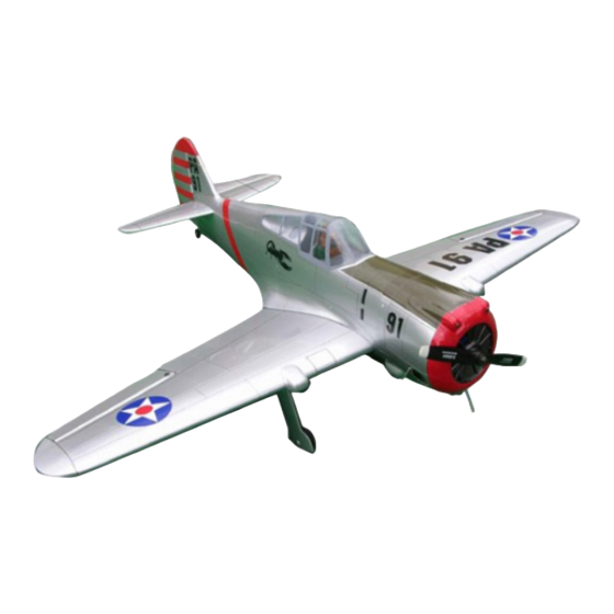
SPECIFICATION
1 Wingspan : 1,600 mm
1 Length
1 Weight
Parts listing required (not included):
1 Engine
1 Servo
1 Radio
Instruction Manual Book
: 1,300 mm
: 3.9 kg
: 61 cu.in - 2stroke;
15 CC Gas.
: 8 Servos + 2 servos Retract (HITEC HS-75BB).
: 8 channels.
63.in.
52.in.
8.58 lbs.
ITEM CODE:BH41-A
Made in Vietnam.
Advertisement
Table of Contents

Subscribe to Our Youtube Channel
Related Manuals for Black Horse Model P-36A HAWK


Summary of Contents for Black Horse Model P-36A HAWK
- Page 1 Instruction Manual Book ITEM CODE:BH41-A SPECIFICATION 1 Wingspan : 1,600 mm 63.in. 1 Length : 1,300 mm 52.in. 1 Weight : 3.9 kg 8.58 lbs. Parts listing required (not included): 1 Engine : 61 cu.in - 2stroke; 15 CC Gas. 1 Servo : 8 Servos + 2 servos Retract (HITEC HS-75BB).
- Page 2 P- 36A HAWK-Item code BH41-A. INSTRUCTION MANUAL. This instruction manual is designed to help you build a great flying aeroplane. Please read this manual thoroughly before starting assembly of your P- 36A HAWK. Use the parts listing below to identify all parts. WARNING.
-
Page 3: Safety Precaution
P- 36A HAWK-Item code BH41-A. INSTRUCTION MANUAL. SAFETY PRECAUTION. + This is not a toy + Be sure that no other flyers are using your radio frequency. + Do not smoke near fuel. + Store fuel in a cool, dry place, away from children and pets. + Wear safety glasses. -
Page 4: Installing The Aileron Servos
P- 36A HAWK-Item code BH41-A. INSTRUCTION MANUAL. REPLACEMENT SMALL PARTS 3 x 10mm. 3 x 10mm. 3x12mm 1.Door mounting wheel. I. AILERON. 2.Retract main gear. 3.Wheels. 1.INSTALLING THE AILERON SERVOS. 4. Fuel tank. 1 1) Install the rubber grommets and brass 5. - Page 5 P- 36A HAWK-Item code BH41-A. INSTRUCTION MANUAL. Cut the covering away from the slot. Thread. Electric wire Temporary pin to keep hinge centered. Assemble then apply drops of thin 4. Instal servo tray with aileron servo into C/A to center of hinge,on both sides. the wing as same as picture below.
-
Page 6: Installing The Flap Servos
P- 36A HAWK-Item code BH41-A. INSTRUCTION MANUAL. 2 x 8mm Aileron control horn. Secure. Secure. Repeat the procedure for the other wing half. II. FLAP. Aileron control horn. 1.INSTALLING THE FLAP SERVOS. Repeat the procedure for the other wing half. INSTALLING THE AILERON LINKAGES. - Page 7 P- 36A HAWK-Item code BH41-A. INSTRUCTION MANUAL. E l e c t r i c wire Flap control horn. Secure. C/A glue. 2.INSTALLING THE FLAP CONTROL HORN. 3 x 15 mm. C/A glue. Bottom of wing. C/A glue. Secure. C/A glue.
- Page 8 P- 36A HAWK-Item code BH41-A. INSTRUCTION MANUAL. 3.INSTALLING THE FLAP LINKAGES. INSTALLING RETRACTABLE LANDING GEAR. Installing the aileron linkages as pictures below. 2x8mm. 58 mm. 3 x 15mm. 3 x 15mm. 2 x 8mm Secure. Mark point. Aileron Flap bottom of wing. Repeat the procedure for the other wing half.
- Page 9 P- 36A HAWK-Item code BH41-A. INSTRUCTION MANUAL. Mark point. Drill a hole 2mm diameter 3 x 15mm. Secure. Secure. Push.
- Page 10 P- 36A HAWK-Item code BH41-A. INSTRUCTION MANUAL. Servo for retractable only. connector. Secure. Secure.
- Page 11 P- 36A HAWK-Item code BH41-A. INSTRUCTION MANUAL. Drill a hole 2mm 3 x 10mm. diameter Remove covering. 3 x 10mm. Secure. Trim and cut. Secure. Drill a hole 2mm diameter...
-
Page 12: Installing The Engine Mount
P- 36A HAWK-Item code BH41-A. INSTRUCTION MANUAL. INSTALLING THE ENGINE. See pictures below: 5 x30mm. Bottom side. Repeat the procedure for the other wing half. INSTALLING THE ENGINE MOUNT. See pictures below: Drill a hole 5.2mm diameter Secure. -
Page 13: Installing The Throttle - Cable
P- 36A HAWK-Item code BH41-A. INSTRUCTION MANUAL. Throttle servo INSTALLING THE THROTTLE - CABLE. 1. Install one adjustable metal connector Throttle cable through the third hole out from the center of one servo arm, enlarge the hole in the servo arm using a 2mm drill bit to accommodate the servo connector. - Page 14 P- 36A HAWK-Item code BH41-A. INSTRUCTION MANUAL. 3. Carefully bend the second nylon tube up 7. Using a modeling knife, cut 3 lengths of at a 45 degree angle (using a cigarette lighter). fuel line 150mm long. Connect 2 lines to the 2 This tube will be the vent tube to the muffler.
- Page 15 P- 36A HAWK-Item code BH41-A. INSTRUCTION MANUAL. COWLING. See pictures below: Fuel tank. Tie wrap.
- Page 16 P- 36A HAWK-Item code BH41-A. INSTRUCTION MANUAL. center 2. Mark point 1. center 1. Mark point 3. Center 3. Trim and cut. Mark point 2.
- Page 17 P- 36A HAWK-Item code BH41-A. INSTRUCTION MANUAL. 4 1) Slide the fiberglass cowl over the en- gine and line up the back edge of the cowl with 3x 12mm. the marks you made on the fuselage. 1 2. While keeping the back edge of the cowl flush with the marks, align the front of the cowl with the crankshaft of the engine.
-
Page 18: Horizontal Stabilizer
P- 36A HAWK-Item code BH41-A. INSTRUCTION MANUAL. ELEVATOR INSTALLING SERVOS. Temporary pin to keep hinge centered. Assemble then apply drops of thin C/A to center of hinge,on both sides. Elevator servo. Elevator servo. HORIZONTAL STABILIZER. See pictures below: 9 mm 142 mm Cut the covering away from the slot. - Page 19 P- 36A HAWK-Item code BH41-A. INSTRUCTION MANUAL. ELEVATOR CONTROL HORN INSTALLATION. Elevator control horn install as same as the way of aileron control horn. Please see pic- tures below. 3 x 20 mm. Secure. Epoxy glue Bottom side Elevator Control horn. C/A glue.
- Page 20 P- 36A HAWK-Item code BH41-A. INSTRUCTION MANUAL. Secure. Plastic parts of elevator and rudder pushrod. Secure. Elevator Elevator pushrod pushrod Bottom side. Elevator pushrod. 2 x8mm Secure. C/A glue.
-
Page 21: Vertical Installation
P- 36A HAWK-Item code BH41-A. INSTRUCTION MANUAL. Bottom side. Cut the covering away from the slot. VERTICAL INSTALLATION. Temporary pin to keep hinge centered. Rudder Servo. Assemble then apply drops of thin C/A to center of hinge,on both sides. Hinge. Bottom side. -
Page 22: Rudder Pushrod Installation
P- 36A HAWK-Item code BH41-A. INSTRUCTION MANUAL. RUDDER CONTROL HORN INSTALLATION. Secure. Rudder control horn install as same as the way of aileron control horn. Please see pic- tures below. Control horn of Rudder. 3 x 30mm. 2 x 8mm. Secure. -
Page 23: Mounting The Tail Wheel Bracket
P- 36A HAWK-Item code BH41-A. INSTRUCTION MANUAL. 1 2. Mark the locations of the two mounting screws. Remove the tail wheel bracket and drill 2mm pilot holes at the locations marked. Rudder pushrod. Elevator pushrod. Bottom side. MOUNTING THE TAIL WHEEL BRACKET. -
Page 24: Installing The Switch
P- 36A HAWK-Item code BH41-A. INSTRUCTION MANUAL. C/A glue. Mark line. Bottom side. Remove covering. Top side. INSTALLING THE SWITCH. 1 1. Cut out the switch hole using a modeling knife. Use a 2mm drill bit and drill out the two mounting holes through the fuselage side. -
Page 25: Wing Attachment
P- 36A HAWK-Item code BH41-A. INSTRUCTION MANUAL. Switch. Battery of receiver. Switch of receiver. Switch of engine. Battery of engine. INSTALLING THE RECEIVER AND BATTERY. Tie wrap. 1 1. Plug the servo leads and the switch lead into the receiver. You may want to plug an aileron extension into the receiver to make plugging in the aileron servo lead easier when you are installing the wing . - Page 26 P- 36A HAWK-Item code BH41-A. INSTRUCTION MANUAL. Right wing. Secure. Right wing. Secure. bottom side. Left wing. Top side. 3x 15mm. Top side. bottom side. secure.
-
Page 27: Control Throws
4 4) Check the control surface. 4 5) Check the receiver antenna . It should be fully extended and not coiled up inside the fuselage. 4 6) Properly balance the propeller. We wish you many safe and enjoy- able flights with your P-36A HAWK...
Need help?
Do you have a question about the P-36A HAWK and is the answer not in the manual?
Questions and answers