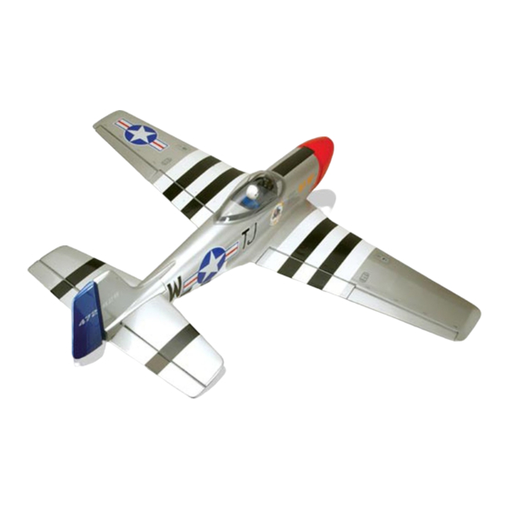
Black Horse Model Mustang P51 Instruction Manual
Mustang p51
Hide thumbs
Also See for Mustang P51:
- Instruction manual book (35 pages) ,
- Instruction manual book (20 pages)
Table of Contents
Advertisement
Quick Links
Instruction Manual book
SPECIFICATION
Wingspan :
Length
Weight
Parts listing required (not included).
Radio
Servo
Engine
1,560 mm
:
1,360 mm
:
3.2 kg
:
06 channels.
:
07 Servos+2 servos Retract (FUTABA,S3170G)
:
61 Cu.in
91 Cu.in
61.42 in.
53.54 in.
7.04 Lbs.
2 Stroke.
4 Stroke.
Made in Vietnam.
Item code BH33-A.
Advertisement
Table of Contents

Subscribe to Our Youtube Channel
Related Manuals for Black Horse Model Mustang P51


Summary of Contents for Black Horse Model Mustang P51
- Page 1 Instruction Manual book Item code BH33-A. SPECIFICATION Wingspan : 1,560 mm 61.42 in. Length 1,360 mm 53.54 in. Weight 3.2 kg 7.04 Lbs. Parts listing required (not included). ...
-
Page 2: Parts List
Instruction Manual Item code: BH33-A . This instruction manual is designed to help you build a great flying aeroplane. Please read this manual thoroughly before starting assembly of your MUSTANG P51. Use the parts listing below to identify all parts. WARNING. -
Page 3: Safety Precaution
MUSTANG P51 - Instruction Manual Item code: BH33-A . SAFETY PRECAUTION. Caution: this model is not a toy! + This is not a toy If you are a beginner to this type of powered + Be sure that no other flyers are using your model, please ask an experienced model flyer radio frequency. -
Page 4: Installing The Aileron Servos
MUSTANG P51 - Instruction Manual Item code: BH33-A . 1.Door mounting wheel. 2. Wheels. Temporary pin to 3. Air retract main gear. keep hinge centered. 4. Spinner 5. Plastic part of wing 6.Plastic - enginemount. 7. Fuel tank. 8.Tail gear set. -
Page 5: Installing The Aileron Linkages
MUSTANG P51 - Instruction Manual Item code: BH33-A . 3) Using the thread as a guide and using INSTALLING THE AILERON CONTROL HORN. masking tape, tape the servo lead to the end of the thread: carefully pull the thread out. - Page 6 MUSTANG P51 - Instruction Manual Item code: BH33-A . Snap keeper. Drill a hole 1.7mm Aileron servo 4. Locate one nylon servo arm, and using wire cutters,remove all but one of the arms. Using a 2mm drill bit, enlarge the third hole INSTALLING THE FLAP SERVO.
- Page 7 MUSTANG P51 - Instruction Manual Item code: BH33-A . INSTALLING THE FLAP LINKAGES. Installing the flap linkages as pictures Drill a hole 1.5mm 100mm Snap keeper Secure. Drill a hole 1.5mm diameter. INSTALLING THE FLAP CONTROL HORN Bend. A+B Epoxy PLUS glue.
- Page 8 MUSTANG P51 - Instruction Manual Item code: BH33-A . 4x12mm Secure Bottom of wing Aileron servo Flap servo Aileron Flap Repeat the procedure for the other wing half. INSTALLING RETRACTABLE LANDING GEAR. 3x6mm. 3x6mm. 3x4mm. 3x4mm. Mark point and Drill a 3x15mm.
- Page 9 MUSTANG P51 - Instruction Manual Item code: BH33-A . secure. Secure 5x35mm.
- Page 10 MUSTANG P51 - Instruction Manual Item code: BH33-A . Secure Secure Drill a hole 3mm Secure hole 3mm 3x6mm 3x8mm...
- Page 11 MUSTANG P51 - Instruction Manual Item code: BH33-A . Secure 3x12mm Secure...
-
Page 12: Installing The Engine Mount
MUSTANG P51 - Instruction Manual Item code: BH33-A . C/A glue INSTALLING THE ENGINE MOUNT. See pictures below: Drill a hole 5mm diameter ENGINE MOUNT. -
Page 13: Installing The Stopper Assembly
MUSTANG P51 - Instruction Manual Item code: BH33-A . 4 X 30mm Fuel pick- up tube Vent tube Fuel fill tube 5) Test fit the stopper assembly into the tank. It may be necessary to remove some of the flashing around the tank opening using a modeling knife. -
Page 14: Installing The Engine
MUSTANG P51 - Instruction Manual Item code: BH33-A . Do not secure the tank into place perma- nently until after balancing the airplane. You may need to remove the tank to mount the Mark point battery in the fuel tank compartment Tie wrap. -
Page 15: Installing The Throttle Pushrod
MUSTANG P51 - Instruction Manual Item code: BH33-A . Left side Secure. INSTALLING THE THROTTLE PUSHROD. Install one adjustable metal connector through the third hole out from the center of one servo arm, enlarge the hole in the servo arm using a 2mm drill bit to accommodate the servo connector. -
Page 16: Installing The Spinner
MUSTANG P51 - Instruction Manual Item code: BH33-A . 4) Install the muffler and muffler extension onto the engine and make the cutout in the cowl for muffler clearance. Connect the fuel and pressure lines to the carburetor, muffler and fuel filler valve. -
Page 17: Horizontal Stabilizer Installation
MUSTANG P51 - Instruction Manual Item code: BH33-A . ELEVATOR INSTALLATION. SERVO INSTALLATION. Temporary pin to keep hinge centered. 1. Install the rubber grommets and brass collets into the elevator servo. Test fit the servo into the servo tray. -
Page 18: Elevator Control Horn Installation
MUSTANG P51 - Instruction Manual Item code: BH33-A . Remove covering. 3) Mark the shape of the vertical on the left and right sides onto the horizontal stabilizer using a left-tip pen. Top elevator Mark line. Bottom side 5) When you are sure that everything is aligned correctly, mix up a generous amount Mark line. - Page 19 MUSTANG P51 - Instruction Manual Item code: BH33-A . Epoxy glue A+B Epoxy PLUS glue Epoxy glue 6. After the epoxy has fully cured, re- move the masking tape or T-pins used to hold the stabilizer in place and carefully in- spect the glue joints.
-
Page 20: Elevator Pushrod Installation
MUSTANG P51 - Instruction Manual Item code: BH33-A . ELEVATOR PUSHROD INSTALLATION. Elevator pushrod install as same as the way of aileron pushrod. Bend E l e v a t o r pushrod E l e v a t o r... -
Page 21: Rudder Control Horn Installa- Tion
MUSTANG P51 - Instruction Manual Item code: BH33-A . Drill a hole Rudder 1.7mm. control horn. E l e v a t o r Installing CA Hinges for the Pushrod Rudder RUDDER CONTROL HORN INSTALLA- TION. Rudder control horn install as same as the way of aileron control horn. -
Page 22: Rudder Pushrod Installation
MUSTANG P51 - Instruction Manual Item code: BH33-A . Top side RUDDER PUSHROD INSTALLATION. 1. Rudder pushrod install as same as the way of aileron control horn. R u d d e r pushrod Elevator pushrod Botom side MOUNTING THE TAIL WHEEL BRACKET. - Page 23 MUSTANG P51 - Instruction Manual Item code: BH33-A . Bottom of fuselage Rudder pusrod Secure...
-
Page 24: Installing The Switch
MUSTANG P51 - Instruction Manual Item code: BH33-A . Secure Rudder pushrod Elevator pushrod Elevator pushrod INSTALLING THE SWITCH. 1) Cut out the switch hole using a modeling knife. Use a 2mm drill bit and drill out the two mounting holes through the fuselage side. -
Page 25: Joining The Wing Halves
MUSTANG P51 - Instruction Manual Item code: BH33-A . Right wing Battery Receiver Secure JOINING THE WING HALVES. 1) Location the aluminium wing dihedral 3. Insert two wing panels as pictures brace. below. 19 mm 396 mm 2) Test fit the dihedral brace into each wing haft. -
Page 26: Installing Cockpit Fuselage
MUSTANG P51 - Instruction Manual Item code: BH33-A . See picture wing attach to fuselage. INSTALLING COCKPIT FUSELAGE . See picture below: Installing the fuselage hatch as same as pic- ture below. C/A glue. Top side. Secure. E p o x y... -
Page 27: Control Throws
5) Check the receiver antenna . It should 135mm be fully extended and not coiled up inside the fuselage. 6) Properly balance the propeller. We wish you many safe and enjoyable flights with your MUSTANG P51.
Need help?
Do you have a question about the Mustang P51 and is the answer not in the manual?
Questions and answers