Table of Contents
Advertisement
Quick Links
Advertisement
Table of Contents

Subscribe to Our Youtube Channel
Related Manuals for Black Horse Model PITTS


Summary of Contents for Black Horse Model PITTS
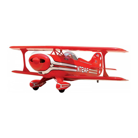
- Page 1 Instruction Manual book SPECIFICATION Wingspan : 1.500 mm 59.06 in. Length : 1.330 mm 52.36 in. Weight : 4.7 kg 10.34 Lbs. Radio : 6 channels.
-
Page 2: Parts List
Instruction Manual ITEM CODE: BH85. This instruction manual is designed to help you build a great flying aeroplane. Please read this manual thoroughly before starting assembly of your PITTS. Use the parts listing below to identify all parts. WARNING Please be aware that this aeroplane is not a toy and if assembled or used incorrectly it is capable of causing injury to people or property. -
Page 3: Safety Precaution
PITTS Instruction Manual ITEM CODE: BH85. Caution: this model is not a toy! SAFETY PRECAUTION. If you are a beginner to this type of powered + This is not a toy model, please ask an experienced model flyer + Be sure that no other flyers are using your for help and support. -
Page 4: Installing The Aileron Servo
PITTS Instruction Manual ITEM CODE: BH85. C/A glue 1. Wheels pants. 2. Main gear . 3. Wheels. 4. Plastic-enginemount. C/A glue 5. Covering of main gear. 6. Tail gear. 7. Plastic for rudder. 8. Spinner. 9. Fuel tank. 10. Wing struts sets. - Page 5 PITTS Instruction Manual ITEM CODE: BH85. 4) Drill 1,6mm pilot holes through the block INSTALLING THE AILERON SERVO . of wood for each of the four mounting screws 1. Install the rubber grommets and brass provided with the servo.
-
Page 6: Installing The Aileron Linkages
PITTS Instruction Manual ITEM CODE: BH85. Aileron control horn Control horn of the aileron INSTALLING THE AILERON LINKAGES. Installing the aileron linkages as pictures below. M2 lock nut 75mm... -
Page 7: Wing Strut Installation
PITTS Instruction Manual ITEM CODE: BH85. C/A glue C/A glue Bottom side C/A glue Repeat the procedure for the right lower wing half. WING STRUT INSTALLATION (UPPER WING). Parts requirement. See pictures below: Bottom side C/A glue... - Page 8 PITTS Instruction Manual ITEM CODE: BH85. 2 x 10mm Secure Repeat the procedure for the right lower wing half (Top of right ).
-
Page 9: Joining The Wing Halves
PITTS Instruction Manual ITEM CODE: BH85. JOINING THE WING HALVES (UPPER MAIN WING). 4 x 30mm 1 1. Locate the aluminium wing dihedral brace. Secure Top right side 2. Test fit the aluminium dihedral brace into each wing half. The brace should slide in easily. -
Page 10: Installing The Engine Mount
PITTS Instruction Manual ITEM CODE: BH85. Top side Bottom side INSTALLING THE ENGINE MOUNT. See pictures below: FUEL TANK. INSTALLING THE STOPPER ASSEMBLY 4 x 30mm 1) The stopper has been pre-assembled at the factory. 2) Using a modeling knife, cut one length... - Page 11 PITTS Instruction Manual ITEM CODE: BH85. When the stopper assembly is installed in the tank, the top of the vent tube should rest just below the top surface of the tank. It should not touch the top of the tank.
-
Page 12: Installing The Engine
PITTS Instruction Manual ITEM CODE: BH85. Mark Fuel tank point Drill a hole 4mm diameter INSTALLING THE ENGINE. Pushrod wire. Locate the long piece of wire used for the throttle pushrod. One end of the wire has been pre-bend in to a “Z” bend at the factory. This “Z”... - Page 13 PITTS Instruction Manual ITEM CODE: BH85. 2) While keeping the back edge of the Pushrod cowl flush with the marks, align the front of w i r e . the cowl with the crankshaft of the engine. The front of the cowl should be positioned so the crankshaft is in nearly the middle of the cowl opening.
-
Page 14: Installing The Throttle Pushrod
PITTS Instruction Manual ITEM CODE: BH85. Botton side Trim and cut Secure Left side INSTALLING THE THROTTLE PUSHROD. Install one adjustable metal connector through the third hole out from the center of Top side one servo arm, enlarge the hole in the servo arm using a 2mm drill bit to accommodate the servo connector. -
Page 15: Horizontal Stabilizer
PITTS Instruction Manual ITEM CODE: BH85. HORIZONTAL STABILIZER. See pictures below: Secure C/A glue ELEVATOR INSTALLATION. SERVO INSTALLATION. 1. Install the rubber grommets and brass collets into the elevator servo. Test fit the servo into the servo tray. 2. Mount the servo to the tray using the ... - Page 16 PITTS Instruction Manual ITEM CODE: BH85. C/A glue Remove covering C/A glue 3. Mark the shape of the vertical on the left and right sides onto the horizontal stabilizer using a left-tip pen. C/A glue 1. Draw a center line onto the horizontal ...
- Page 17 PITTS Instruction Manual ITEM CODE: BH85. 4. Remove the stabilizer. Using the lines you just drew as a guide, carefully remove the Epoxy glue covering from between them using a modeling knife. When cutting through the covering to remove it, cut with only enough pressure to only cut through the covering it’s self.
-
Page 18: Elevator Pushrod Installation
PITTS Instruction Manual ITEM CODE: BH85. ELEVATOR PUSHROD INSTALLATION. C/A glue C/A glue ELEVATOR CONTROL HORN INSTALLATION. Elevator control horn install as same as the way of aileron control horn. Please see pic- tures below. 3mm x 40mm. M3 lock nut. - Page 19 PITTS Instruction Manual ITEM CODE: BH85. Secure E l e v a t o r E l e v a t o r pushrod pushrod...
-
Page 20: Vertical Installation
PITTS Instruction Manual ITEM CODE: BH85. VERTICAL INSTALLATION. 1) Using a modeling knife, remove the covering from the top of the fuselage and the Rudder servo install as same as method of elevator servo. See picture below: covering from over the precut hinge slot cut into the lower rear portion of the fuselage This slot accepts the lower vertical. - Page 21 PITTS Instruction Manual ITEM CODE: BH85. C/A glue Epoxy glue Epoxy glue Hinge slot. 5. Put the vertical stabilizer back in place. Using a triangle, check to ensure that the vertical stabilizer is aligned 90 de- gree to the horizontal stabilizer.
-
Page 22: Rudder Control Horn Installa- Tion
PITTS Instruction Manual ITEM CODE: BH85. 6) When you are sure that everything is a aligned correctly, mix up a generous amount of 30 minute epoxy. Apply a thin layer to the slot in the mounting platform and to the verti- cal stabilizer mounting area. -
Page 23: Rudder Pushrod Installation
PITTS Instruction Manual ITEM CODE: BH85. RUDDER PUSHROD INSTALLATION. Rudder pushrod install as same as the way MOUNTING THE TAIL WHEEL of aileron pushrod. BRACKET. 1. Set the tail wheel assembly in place on the plywood plate. The pivot point of the... - Page 24 PITTS Instruction Manual ITEM CODE: BH85. 2. Using a pen, mark the locations of the two mounting screws. Remove the tail wheel bracket and drill 1mm pilot holes at the loca- tions marked. Mark point Cut.
- Page 25 PITTS Instruction Manual ITEM CODE: BH85. INSTALLING THE MAIN LANDING GEAR. PARTS REQUIRED Secure 2 b. 2 a. 3 x 15mm C/A glue C/A glue C/A glue C/A glue Drill a hole 2mm diametter...
-
Page 26: Installing The Switch
PITTS Instruction Manual ITEM CODE: BH85. Secure Secure Drill a hole 5mm diametter Secure INSTALLING THE SWITCH. 1) Cut out the switch hole using a modeling knife. Use a 2mm drill bit and drill out the two mounting holes through the fuselage side. -
Page 27: Installing The Receiver And Battery
PITTS Instruction Manual ITEM CODE: BH85. Tie wrap. Receiver switch WING ATTACHMENT. INSTALLING THE RECEIVER AND BATTERY. Locate the aluminium wing dihedral brace. 1. Plug the servo leads and the switch lead into the receiver. You may want to plug... - Page 28 PITTS Instruction Manual ITEM CODE: BH85. WING ATTACHMENT. See picture wing attach to fuselage. Wing bolt. Installing the fuselage hatch as same as pic- ture below. Drill a hole 3mm diameter Drill a hole 3mm diameter Secure 4 x 30mm...
- Page 29 PITTS Instruction Manual ITEM CODE: BH85. 3 x 12mm Secure Secure Secure...
-
Page 30: Control Throws
5) Check the receiver antenna . It should be fully extended and not coiled up inside the fuselage. 6) Properly balance the propeller. We wish you many safe and enjoyable flights with your PITTS .
Need help?
Do you have a question about the PITTS and is the answer not in the manual?
Questions and answers