Table of Contents
Advertisement
Quick Links
Advertisement
Table of Contents

Related Manuals for Black Horse Model P.C-9 BH76


Summary of Contents for Black Horse Model P.C-9 BH76
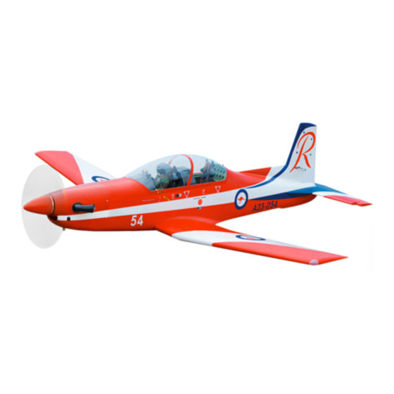
- Page 1 Instruction Manual book SPECIFICATION Wingspan : 1,840 mm 72.44 in. Length 1,830 mm 72.05 in. Weight 5.3 kg 11.66 Lbs. Radio 06 channels.
-
Page 2: Parts List
P.C-9 Instruction Manual. - Item code: BH76. This instruction manual is designed to help you build a great flying aeroplane. Please read this manual thoroughly before starting assembly of your P.C-9. Use the parts listing below to identify all parts. WARNING Please be aware that this aeroplane is not a toy and if assembled or used incorrectly it is capable of causing injury to people or property. -
Page 3: Safety Precaution
P.C-9 Instruction Manual. - Item code: BH76. Caution: this model is not a toy! SAFETY PRECAUTION. If you are a beginner to this type of powered + This is not a toy model, please ask an experienced model flyer + Be sure that no other flyers are using your for help and support. -
Page 4: Installing The Aileron Servos
P.C-9 Instruction Manual. - Item code: BH76. Aileron Flap Bottom side C/A glue 1. Air retract (Nose gear). 2. Air retracts (Main gear). 3. Wheels. Bottom side 4. Valve control. 5. Air line sets. 6. Valve one way. 7. 4 way connector. 8. - Page 5 P.C-9 Instruction Manual. - Item code: BH76. C/A glue Bottom side C/A glue Bottom side 2) Using a modeling knife, remove the cov- ering at possition show below. C/A glue Remove covering C/A glue...
- Page 6 P.C-9 Instruction Manual. - Item code: BH76. 2x10mm. Secure Secure 2.INSTALLING THE AILERON CONTROL HORN. 3) Using the thread as a guide and using masking tape, tape the servo lead to the end of the thread: carefully pull the thread out. When you have pulled the servo lead out, re- 3mm x 40mm.
-
Page 7: Installing The Aileron Linkages
P.C-9 Instruction Manual. - Item code: BH76. Remove covering Elevator control horn Repeat the procedure for the other wing half. INSTALLING THE AILERON LINKAGES. Installing the aileron linkages as pictures below. M3 lock nut 70mm... - Page 8 P.C-9 Instruction Manual. - Item code: BH76. C/A glue Thread Electric way C/A glue 2x10mm. INSTALLING THE FLAP SERVO . Secure Bottom side...
- Page 9 P.C-9 Instruction Manual. - Item code: BH76. INSTALLING THE FLAP CONTROL HORN. Nilon control clasp. M3 lock nut 3 x 40mm Flap control horn. Repeat the procedure for the other wing half. INSTALLING THE FLAP LINKAGES. Installing the flap linkages as pictures Remove covering below.
- Page 10 P.C-9 Instruction Manual. - Item code: BH76. C/A glue 3x15mm 3x15mm Bottom of left wing. Mark point Bottom of right wing. Repeat the procedure for the other wing half. INSTALLING AIR RETRACTABLE LANDING GEAR.
- Page 11 P.C-9 Instruction Manual. - Item code: BH76. C/A glue 3 x 15mm Epoxy glue Secure Epoxy glue...
-
Page 12: Wing Attachment
P.C-9 Instruction Manual. - Item code: BH76. Bottom side Top side WING ATTACHMENT. 1Locate the aluminium wing dihedral brace. Secure *** Test fit the aluminium tube dihedral brace into each wing haft. The brace should slide in easily. If not, use 220 grit sand around the edges and ends of the brace until it fits prop- erly. -
Page 13: Installing The Engine Mount
P.C-9 Instruction Manual. - Item code: BH76. Secure Drill a hole 3mm diameter 4 x 30mm INSTALLING THE ENGINE MOUNT. See pictures below: Secure 4 x 30mm 4 x 30mm Drill a hole 3mm diameter... -
Page 14: Installing The Stopper Assembly
P.C-9 Instruction Manual. - Item code: BH76. Drill a hole 2mm diameter When the stopper assembly is installed in the tank, the top of the vent tube should rest just below the top surface of the tank. It should not touch the top of the tank. -
Page 15: Installing The Engine
P.C-9 Instruction Manual. - Item code: BH76. 6) When satisfied with the alignment of the stopper assembly tighten the 3mm x 20mm machine screw until the rubber stopper ex- pands and seals the tank opening. Do not over tighten the assembly as this could cause the tank to split. - Page 16 P.C-9 Instruction Manual. - Item code: BH76. 145mm Pushrod wire 4 x 30mm Secure Mark point Drill a hole 4mm diameter. Left side Right side...
- Page 17 P.C-9 Instruction Manual. - Item code: BH76. COWLING. Bottom side Trim and cut Top side Trim and cut Left side Bottom side 1. Slide the fiberglass cowl over the en- Right side gine and line up the back edge of the cowl with the marks you made on the fuselage.
-
Page 18: Installing The Throttle Pushrod
P.C-9 Instruction Manual. - Item code: BH76. Bottom side Bottom side INSTALLING THE THROTTLE PUSHROD. Install one adjustable metal connector through the third hole out from the center of one servo arm, enlarge the hole in the servo arm using a 2mm drill bit to accommodate the servo connector. -
Page 19: Horizontal Stabilizer
P.C-9 Instruction Manual. - Item code: BH76. ELEVATOR INSTALLATION. SERVO INSTALLATION. 1. Install the rubber grommets and brass collets into the elevator servo. Test fit the servo into the servo tray. 2. Mount the servo to the tray using the ... - Page 20 P.C-9 Instruction Manual. - Item code: BH76. Remove covering C/A glue 3. Mark the shape of the vertical on the left and right sides onto the horizontal stabilizer using a left-tip pen. C/A glue 1. Draw a center line onto the horizontal ...
- Page 21 P.C-9 Instruction Manual. - Item code: BH76. Remove covering C/A glue C/A glue Check to mark sure the wing and stabi- lizer are paralell. If they are not, lightly sand the opening in the fuselage for the stabilizer until the stabilizer is paralell to the wing. Epoxy glue ELEVATOR AND RUDDER PUSHROD INSTALLATION.
- Page 22 P.C-9 Instruction Manual. - Item code: BH76. Remove covering 3 x 40mm. Nilon control clasp. M3 lock nut. Remove covering...
-
Page 23: Vertical Installation
P.C-9 Instruction Manual. - Item code: BH76. M2 lock nut. VERTICAL INSTALLATION. Rudder servo install as same as method of elevator servo. See picture below:... - Page 24 P.C-9 Instruction Manual. - Item code: BH76. 3. Put the vertical stabilizer back in place. Using a triangle, check to ensure that the vertical stabilizer is aligned 90 de- gree to the horizontal stabilizer. C/A glue Mark point ...
- Page 25 P.C-9 Instruction Manual. - Item code: BH76. Remove covering C/A glue Top side 5) When you are sure that everything is a aligned correctly, mix up a generous amount of 30 minute epoxy. Apply a thin layer to the slot in the mounting platform and to the verti- cal stabilizer mounting area.
- Page 26 P.C-9 Instruction Manual. - Item code: BH76. Epoxy glue Remove covering C/A glue C/A glue...
- Page 27 P.C-9 Instruction Manual. - Item code: BH76. INSTALLING NOSE AIR RETRACTABLE LANDING GEAR. Secure...
- Page 28 P.C-9 Instruction Manual. - Item code: BH76. Secure 3 x 15mm...
- Page 29 P.C-9 Instruction Manual. - Item code: BH76. Throttle servo Elevator servo Nose gear servo Rudder servo INSTALLING SERVO USING FOR VALVE CONTROL Servo valve control. Secure...
- Page 30 P.C-9 Instruction Manual. - Item code: BH76. 3 way conector Air tank Air supply Valve one way Nose gear 4 way conector 4 way conector Left main gear wing Right main gear wing Secure Valve control 3 way conector Valve one way 4 way conector...
-
Page 31: Installing The Receiver And Battery
P.C-9 Instruction Manual. - Item code: BH76. Tie wrap. INSTALLING THE RECEIVER AND BATTERY. 1. Plug the servo leads and the switch lead into the receiver. You may want to plug an aileron extension into the receiver to make plugging in the aileron servo lead easier when you are installing the wing . - Page 32 P.C-9 Instruction Manual. - Item code: BH76.
- Page 33 P.C-9 Instruction Manual. - Item code: BH76. Battery Remove covering Receiver WING ATTACHMENT. See picture wing attach to fuselage. Wing bolt.
- Page 34 P.C-9 Instruction Manual. - Item code: BH76. Plastic parts bottom side of Remove covering fuselage. Installing the fuselage hatch as same as pic- ture below. Mark line Remove covering Bottom side Bottom side C/A glue Remove covering...
- Page 35 P.C-9 Instruction Manual. - Item code: BH76. C/A glue C/A glue Plastic parts top side pushrod. Remove covering C/A glue...
- Page 36 P.C-9 Instruction Manual. - Item code: BH76. Marrk line C/A glue C/A glue Plastic parts top side of fuselage. Mark point...
- Page 37 P.C-9 Instruction Manual. - Item code: BH76. C/A glue C/A glue BALANCING. Remove covering 1) It is critical that your airplane be bal- anced correctly. Improper balance will cause your plane to lose control and crash. THE CENTER OF GRAVITY IS LOCATED 72MM BACK FROM THE LEADING EDGE OF THE WING.
-
Page 38: Pre-Flight Check
P.C-9 Instruction Manual. - Item code: BH76. Accurately mark the balance point on the top of the wing on both sides of the fuselage. The balance point is located 72mm back from the leading edge. This is the balance point at which Ailerons Control your model should balance for your first flights.
Need help?
Do you have a question about the P.C-9 BH76 and is the answer not in the manual?
Questions and answers