Table of Contents
Advertisement
Quick Links
Instruction Manual Book
Glow and EP
OPTION ELECTRIC RETRACT GEAR (NOT INCLUDING).
ONLY INCLUDING CNC SUSPENSION METAL STRUTS.
ALL BALSA - PLYWOOD CONSTRUCTION.
COVERED WITH ORACOVER.
95% ALMOST READY TO FLY
SPECIFICATION:
- Wingspan: 1,840 mm (72.44 in).
- Length: 1,850 mm (72.83 in).
- Weight: 5.3 - 5.6 kg (11.66 - 12.32 lbs).
- Wing area: 54.6 dm
.
2
- Wing loading: 97.07 g/dm
- Servo mount: 42mm x 21mm.
- Wing type: Naca Airfoil.
- Gear type: Electric retract gear,
size: (92.2 x 51 x 30.6)mm (not included).
CNC Suspension Metal Struts (included).
- Spinner: 80mm.
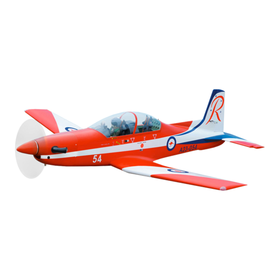
PC-9
.
2
Item code: BH76
Parts listing required (not included):
- Radio: 07 channels.
- Servo: 08 servos.
- Engine: 120 - 2 stroke, 20 - 30cc gas.
- Motor: Brushless outrunner 1800-2300W, 250-450KV.
- Propeller: Suit with your engine.
Recommended motor and battery set up
(not included):
- Motor: Admiral GP20 6320-295kV
- Lipo cell: 6-8 cells 4,000-5,000mAh.
- Receiver battery: 6V/ 1200-2000mAh.
- ESC: 90-120A.
Made in Vietnam
Advertisement
Table of Contents

Related Manuals for Black Horse Model PC-9


Summary of Contents for Black Horse Model PC-9
- Page 1 Instruction Manual Book Item code: BH76 PC-9 Glow and EP OPTION ELECTRIC RETRACT GEAR (NOT INCLUDING). ONLY INCLUDING CNC SUSPENSION METAL STRUTS. ALL BALSA - PLYWOOD CONSTRUCTION. COVERED WITH ORACOVER. 95% ALMOST READY TO FLY SPECIFICATION: Parts listing required (not included): - Wingspan: 1,840 mm (72.44 in).
-
Page 2: Table Of Contents
Thank you for purchasing Black Horse Model products. With over 18 years experience in production and fly testing, Black Horse Model is committed to bring the best quality products and good service to customers. Along with a team of creative engineers and skilled workers, we will always accompany with customers by our great experiences, fully enthusiasm... -
Page 3: Warranty
Please strictly follow the instruction manual to assemble work area thoroughly after working with berglass parts. and use this. In that Black Horse Model has no control over the nal SUGGESTION assembly or material used for nal assembly, Black Horse Model is not responsible for loss of use , or other incidental or consequential damages. -
Page 4: Covering Tools
INSTRUCTION MANUAL PC-9 Item code: BH76 ADHESIVES AND REQUIRED TOOLS FLIGHT WARNINGS When ready to y, rst extend the transmitter aerial. Thin CA Switch on the transmitter. 30-minute epoxy Switch on the receiver. 6-minute epoxy Check that the wings are correctly tted to the fuselage. - Page 5 INSTRUCTION MANUAL PC-9 Item code: BH76 • Officially designated AMA Air Show Teams (AST) are authorized to use devices and practices as defined within the Team AMA Program Document. (AMA Document #718.) (j) Not operate a turbine-powered aircraft, unless in compliance with the AMA turbine regulations. (AMA Document #510-A.)
-
Page 6: Parts Listing (Not Included)
INSTRUCTION MANUAL PC-9 Item code: BH76 PARTS LISTING (NOT INCLUDED) Servo extension leads....2 pcs....1 pcs. 540mm ..4 pcs. 220mm ..2 pcs. Engine: NGH GT-25cc 2 stroke or NGH GF-30cc 4 stroke reccomended 190mm ..3 pcs. - Page 7 INSTRUCTION MANUAL PC-9 Item code: BH76 : Fuselage. : Wing panel (2a, 2b). Canopy, 3b : Pilot, 3c: Cockpit). : Cockpit fuselage (3a: : Horizontal stabilizer. : Vertical stabilizer. : Cowling. : Spinner ( 80mm ). : Aluminium wing dihedral brace.
-
Page 8: Preparations
INSTRUCTION MANUAL PC-9 Item code: BH76 PREPARATIONS: Use a covering iron with a covering sock on hign heat to tighten the covering if necessary. Apply pressure over sheeted areas to thoroughly bond the covering to the wood INSTALLING THE AILERONS AND FLAPS... - Page 9 INSTRUCTION MANUAL PC-9 Item code: BH76 For Flap servo. For Aileron servo. Bottom view Aileron Aileron servos. 2 mm approx.16mm 2x10mm Screw For Aileron. 1.5 mm For Aileron. Screw 1.5 mm 1.5mm 2x10mm Tp Screw Warning! - - - - 16 For Aileron.
-
Page 10: Installing The Control Horns And Linkages
INSTRUCTION MANUAL PC-9 Item code: BH76 Bottom view INSTALLING THE CONTROL HORNS AND LINKAGES 1.7x8mm Cap Screw - - - 4 Nylon Clevis - - - 4 Horn 100mm Push rod - - 4 Flaslink - - - - - - 4... - Page 11 INSTRUCTION MANUAL PC-9 Item code: BH76 Control Horn Servo arm Push rod Flaslink Mark the spot to attach Bend 90 Bottom view Apply instant glue (C.A glue, super glue). C . A Assemble left and right Cut off shaded portion sides the same way.
-
Page 12: Installing The Wheel Well
INSTRUCTION MANUAL PC-9 Item code: BH76 Top view INSTALLING THE WHEEL WELL Using a modeling knife, carefully remove the film covering Wheel well from the gear tray. Make sure that you do not remove any wood. Cut the plastic Cut the plastic... -
Page 13: Main Gear Struts
INSTRUCTION MANUAL PC-9 Item code: BH76 MAIN GEAR STRUTS 3x15mm Cap Screw ELECTRIC NOT INCLUDED. - - - - 8 5x35mm Socket Head Cap Screw - - - - - - 2 5mm Flat washer - - - - - - - - 2 2 pcs. -
Page 14: Electric Gear Retracts
INSTRUCTION MANUAL PC-9 Item code: BH76 Screw the gear in position ELECTRIC GEAR RETRACTS Screw 3x15mm Bottom view 2.5mm The number of times Drill holes using the stated. Assemble left and right the same way Assembly (in this case 2.5mm 2.5mm... - Page 15 INSTRUCTION MANUAL PC-9 Item code: BH76 Screw the gear in position Top view...
-
Page 16: Installing The Fuselage Servos
INSTRUCTION MANUAL PC-9 Item code: BH76 INSTALLING THE FUSELAGE SERVOS Install the rubber grommets and brass collets into the elevator, rudder and throttle servos. Test fit the servos into the servo tray. Trim the tray if necessary to fit your servos. -
Page 17: Installing Horizontal Stabilizer
INSTRUCTION MANUAL PC-9 Item code: BH76 INSTALLING HORIZONTAL STABILIZER 1) Hinges for Elevator are glued the same way as the aileron before (see page 8). When cutting through the covering to 2) Draw a center line onto the horizontal stabilizer remove it, cut with only enough pressure to only cut through the covering it's self. - Page 18 INSTRUCTION MANUAL PC-9 Item code: BH76 1.7x8mm Cap Screw - - -1 Nylon Clevis Horn - - - 1 900mm Push rod - - 1 Flaslink - - - - - - 1 Horn - - - - - - 1...
-
Page 19: Installing The Vertical Stabilizer
INSTRUCTION MANUAL PC-9 Item code: BH76 INSTALLATION THE VERTICAL STABILIZER 1.7x8mm Cap Screw 1) Hinges and servo for Rudder are - - -1 glued the same way as the aileron Nylon Clevis before (see page 8). - - - 1... - Page 20 INSTRUCTION MANUAL PC-9 Item code: BH76 Apply instant glue (C.A glue, super glue). Apply epoxy glue. Cut off shaded portion carefully.
-
Page 21: Installing The Wheel Well
INSTRUCTION MANUAL PC-9 Item code: BH76 INSTALLING THE WHEEL WELL Using a modeling knife, Wheel well carefully remove the film covering Cut the plastic from the gear tray. Make sure that you do not remove any wood. -
Page 22: Installing The Nose Gear
INSTRUCTION MANUAL PC-9 Item code: BH76 INSTALLING THE NOSE GEAR 3x15mm Tp Screw Cab link ELECTRIC NOT INCLUDED. - - - - - 2 - - - - 4 5x35mm Socket Head M3 Metal Clevis Cap Screw - - - 2... -
Page 23: Electric Gear Retracts
INSTRUCTION MANUAL PC-9 Item code: BH76 Screw OPTION 2: ELECTRIC GEAR RETRACTS Screw 3x6 mm Screw Cable rod Screw Crimp... - Page 24 INSTRUCTION MANUAL PC-9 Item code: BH76 3x15mm 2.5mm Screw the gear in position Screw...
- Page 25 INSTRUCTION MANUAL PC-9 Item code: BH76 Servo tail gear Metal Clevis Cab link Hex Nut Fuselage bottom side Servo nose gear Cut off excess. Must be purchased Cut off shaded portion separately! carefully. Drill holes using the stated. (in this case 2mm...
-
Page 26: Installing The Engine
INSTRUCTION MANUAL PC-9 Item code: BH76 INSTALLATION THE ENGINE 4mm Hex Nut - - - - - - - 8 4x30mm Cap Screw - - - - - - - 8 4mm Flat Washer - - - - - - - 8... - Page 27 INSTRUCTION MANUAL PC-9 Item code: BH76 Fuselage top side 4mm Hex Nut 4x30mm 4mm Flat Washer Cap Screw 145mm Apply threadlocker (screw cement).
-
Page 28: Installing The Stopper
INSTRUCTION MANUAL PC-9 Item code: BH76 INSTALLING THE STOPPER Cut off shaded portion carefully. -
Page 29: Installing The Fuel Tank
INSTRUCTION MANUAL PC-9 Item code: BH76 INSTALLING THE FUEL TANK 5. When satisfied with the alignment of the stopper assembly tighten the 3mm x 20mm machine 1. Using a modeling knife, cut one length of silicon screw until the rubber stopper expands and fuel line (the length of silicon fuel line is seals the tank opening. -
Page 30: Installing The Throttle
INSTRUCTION MANUAL PC-9 Item code: BH76 INSTALLING THE THROTTLE direction. When the throttle stick is moved forward from idle to full throttle, the throttle barrel should also open and close using this motion. If not, - - - - - - 1... -
Page 31: Mounting The Cowl
INSTRUCTION MANUAL PC-9 Item code: BH76 MOUNTING THE COWL 4) While holding the cowl firmly in position, drill 1) Remove the muf f ler and needle valve assembly four 1,6mm pilot holes through both the cowl and from the engine. Slide the fiberglass cowl over the the side edges of the firewall. -
Page 32: Installing The Receiver And Battery
INSTRUCTION MANUAL PC-9 Item code: BH76 3x12mm Tp Screw Top Side - - - - 4 3x12mm Tp Screw Drill holes using the stated. (in this case 2mm INSTALLING THE SWITCH, RECEIVER AND BATTERY . INSTALLING THE SWITCH 1) Plug the servo leads and the switch lead into the receiver. - Page 33 INSTRUCTION MANUAL PC-9 Item code: BH76 Fuselage top side Power Engine Zip tie Fuselage bottom side Receiver Switch Switch Switch Battery Zip tie Must be purchased separately!
-
Page 34: Installing The Electric Motor (Ep Version)
INSTRUCTION MANUAL PC-9 Item code: BH76 Fuselage bottom side INSTALLING THE ELECTRIC MOTOR (EP VERSION) 4mm Flat Washer M4 Blind Nut 4x70mm Socket Head Cap Screw - - - - - 4 - - - - - 4 - - 4... - Page 35 INSTRUCTION MANUAL PC-9 Item code: BH76 Fuselage top side 4mm Flat Washer 4mm Spring Washer 4x70mm Socket Head 10x50mm Plastic Cap Screw Apply threadlocker Must be purchased (screw cement). separately!
-
Page 36: Installing The Cockpit Fuselage
INSTRUCTION MANUAL PC-9 Item code: BH76 INSTALLING COCKPIT FUSELAGE Position the canopy so the rear frame on the canopy is aligned with the rear edge of the cockpit opening. Use canopy glue to secure the canopy to the canopy hatch. Use low-tack tape to hold the canopy in position until the glue fully cures. -
Page 37: Wing Attachment
INSTRUCTION MANUAL PC-9 Item code: BH76 Open/Close Adhesive tape. WING ATTACHMENT 25mm Aluminium tube. 6x45mm Plastic - - - 2 499mm Top view... - Page 38 INSTRUCTION MANUAL PC-9 Item code: BH76 Top view Bottom view 6 x 45mm Screw...
-
Page 39: Installing The Spinner, Propeller
INSTRUCTION MANUAL PC-9 Item code: BH76 Main wing must be inserted and attached completely. Bottom view INSTALLING THE SPINNER, PROPELLER * Install the spinner back-plate, propeller and spinner cone. The spinner cone is held in place using two screws. The propeller should not touch any part of the... - Page 40 INSTRUCTION MANUAL PC-9 Item code: BH76 3x12mm Tp Screw Must be purchased separately!
-
Page 41: Balancing
INSTRUCTION MANUAL PC-9 Item code: BH76 BALANCING 2) If one side of the wing fall, that side is heavier than the opposite. Add small amounts of lead weight to the bottom side of the lighter wing half's It is critical that your airplane be balanced wing tip. -
Page 42: For Your Radio Installation Basic Connection For Airplane And Adjustment Of Servos
INSTRUCTION MANUAL PC-9 Item code: BH76 FOR YOUR RADIO INSTALLATION BASIC CONNECTION FOR AIRPLANE AND ADJUSTMENT OF SERVOS Example of connection For more information, refer to radio system instruction manual. Follow instruction manual of Engine and Battery. Aileron Servo Aileron... -
Page 43: Main Gear Dimensional Detail
INSTRUCTION MANUAL PC-9 Item code: BH76 MAIN GEAR DIMENSIONAL DETAIL NOSE GEAR STRUTS MAIN GEAR STRUTS LANDING GEAR MOUNT. 41mm 31mm 44mm 5.1mm hold 5.1mm hold 25mm 21mm... -
Page 44: Decoration
INSTRUCTION MANUAL PC-9 Item code: BH76 DECORATION Top view Bottom view < Side view > Right ENCLOSURE RELEASE < Side view > Left CLOSED PRESS TO UNLOCK ENCLOSURE RELEASE OPEN RESCUE CLOSED DANGER DANGER DANGER DANGER EJECTION EJECTION EJECTION EJECTION... -
Page 45: Exploded View
INSTRUCTION MANUAL PC-9 Item code: BH76... -
Page 46: I/C Flying Warning
I/C FLYING WARNINGS Always operate in open areas, away from NEVER fly near power lines,aerials or ALWAYS adjust the engine from behind factories, hospitals, schools, buildings other dangerous areas including airports, the propeller, and do not allow any part of and houses etc. -
Page 47: I/C Flying Guide
I/C FLYING GUIDELINES Operate the control sticks on the ALWAYS land the model INTO When ready to fly, first extend transmitter and check that the the wind, this ensures that the the transmitter aerial. control surfaces move freely and in model lands at the slowest possible the CORRECT directions.
Need help?
Do you have a question about the PC-9 and is the answer not in the manual?
Questions and answers