Table of Contents
Advertisement
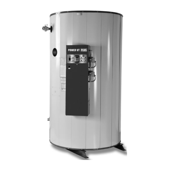
INSTALLATION & MAINTENANCE MANUAL
Installation and service must be performed by a qualified service installer, service agency or the gas supplier.
THIS
MANUAL
IMPORTANT:
MAINTENANCE OF THIS EQUIPMENT. READ AND FOLLOW THE INFORMATION IN THIS MANUAL AND ALL OTHER
PROVIDED INSTRUCTIONS, LABELS AND MARKINGS BEFORE INSTALLING, OPERATING OR SERVICING THIS UNIT.
TO THE INSTALLER: After installation, these instructions must be given to the equipment user or left near the appliance.
SPECIAL INSTRUCTIONS TO THE OWNER: Retain this manual for future reference. These instructions contain
important information that will help you in maintaining and operating this appliance.
POWER VT
MODELS (40, 50, 75, 90, 100) LX 125 A-PVIF
MODELS (50, 75, 90, 100) LX (250, 300) A-PVIF
CONTAINS
INFORMATION
PVI INDUSTRIES, LLC - Fort Worth, Texas 76111 - Web www.pvi.com - Phone 1-800-433-5654
PLUS WATER HEATER
REQUIRED
1
FOR
INSTALLATION,
OPERATION
AND
PV500-44U 06/12
Advertisement
Table of Contents

Related Manuals for PVI Industries POWER VT PLUS


Summary of Contents for PVI Industries POWER VT PLUS
- Page 1 SPECIAL INSTRUCTIONS TO THE OWNER: Retain this manual for future reference. These instructions contain important information that will help you in maintaining and operating this appliance. PVI INDUSTRIES, LLC - Fort Worth, Texas 76111 - Web www.pvi.com - Phone 1-800-433-5654 PV500-44U 06/12 ...
-
Page 2: Table Of Contents
Vertical or Horizontal Remote Air Duct Termination Remote Air Consideration for Combined Remote Air Ducting Venting Venting the Power VT Plus “SANI” Model Venting the Power VT Plus Maximum Category IV Vent Length CPVC Vent System Design, Construction and Assembly... - Page 3 Operating and Safety Controls 10.1 Temperature and Pressure Relief Valve(s) 10.2 Operating Temperature Control 10.3 High Water Temperature Limit Control 10.4 Cathodic Protection 10.5 Electronic Low Water Cut-off (optional) TEMPTRAC Electronic Controller Panel 11.1 Principal of Operation 11.2 Upper LED Readout 11.3 Lower LED Readout 11.4 Control Buttons 11.5 To View the Setpoint...
-
Page 4: Safety Considerations
SAFETY CONSIDERATIONS WARNING: If the information in the supplied manual(s) is not followed exactly, a fire, explosion or exposure to hazardous materials may result, causing property damage, personal injury or loss of life. FOR YOUR SAFETY Do not store or use gasoline or other flammable vapors or liquids in the vicinity of this or any other appliance. WHAT TO DO IF YOU SMELL GAS ... - Page 5 IMPORTANT SAFETY NOTE It takes only 5 seconds of skin contact with 140°F water to cause a second degree burn! You must protect against high water temperatures at all lavatories, tubs, showers and other points of hot water contact. Accidental scalding from high water temperatures is a greater risk in some types of installations.
-
Page 6: Standard Features And Equipment
STANDARD FEATURES AND EQUIPMENT Performance 98% thermal efficiency at full fire from 40° to 140°F Up to 99% thermal efficiency with modulation < 20 ppm NOx (399 to 900 MBH) Ducts direct combustion air up to 100 equivalent feet through 6-inch diameter material (requires UL approved vent cap, see optional equipment list) ... -
Page 7: Product Descriptions
PRODUCT DESCRIPTION Component, Controls and Connection Locations (Locations May Vary) 125 SERIES PV500-44U 06/12 ... - Page 8 250 SERIES PV500-44U 06/12 ...
- Page 9 300 SERIES PV500-44U 06/12 ...
-
Page 10: Water Heater Installation
WATER HEATER INSTALLATION 4.1 Checking Equipment Before You Install Inspect the unit completely upon receipt from the freight carrier before signing the bill of lading. Inspect the appliance and all accompanying parts for signs of impact or mishandling. Verify the total number of pieces shown on packing slips with those actually received. -
Page 11: Service Clearances
8. Do not install on carpet or other combustible floor coverings. If installation over a combustible floor is required, follow these guidelines: Use a base of hollow clay tile or concrete blocks from 8" to 12" thick and extending 24" beyond the sides. ... - Page 12 SINGLE WATER PIPING SINGLE STORAGE WATER HEATER WITH SUPPLEMENTAL STORAGE TANK PV500-44U 06/12 ...
-
Page 13: Condensate Drain, Trap & Disposal
CONDENSATE DRAIN, TRAP & DISPOSAL The POWER VT PLUS water heater is designed to produce significant amounts of condensate because of its high efficiency. Condensate occurs naturally when water vapor in combustion gases is cooled below the dew point. Two 3/4”... -
Page 14: Condensate Neutralization System (Optional)
Condensate Piping and Trap with Optional Condensate Neutralizer 6.1 Condensate Neutralization System (optional) Although only slightly acidic (3-5 PH), condensate can be routed through an optional Condensate Neutralization System (see image below) to become pH neutral allowing for disposal into any drain or sewer system without concern for corrosion. -
Page 15: Gas Supply And Piping
GAS SUPPLY AND PIPING Verify that the type of gas specified on rating plate is supplied to the unit. This unit is orificed for operation up to 2000 feet altitude. Appliance Btuh output derates 4% per 1000 feet elevation above sea level. Consult Factory for installations above 2000 feet elevation. -
Page 16: Appliance Isolation During Gas Supply Piping Pressure Test
Use this corrected total distance from the meter for determining the suggested pipe size in the “Single Unit Installation Suggested Gas Pipe Size” table. SINGLE UNIT INSTALLATION SUGGESTED PIPE SIZE Maximum Capacity for Natural Gas* Equivalent Feet MBTU/HR Based on 0.5" W.C. Pressure Drop** From Meter 1-1/4"... -
Page 17: Gas Connection
7.7 Gas Connection Safe operation of unit requires adequate gas supply with the required static and dynamic (flow) pressures. Actual piping selection depends on many variables that must be carefully considered by the gas piping system designer. Do not select gas pipe sizes based only on the supplied tables. These tables are for use by the gas piping system designer as a reference in checking pipe size selections. -
Page 18: Maximum Allowed Remote Combustion Air Inlet Length
A UL Listed air intake termination cap is available from PVI Industries and may have shipped with the water heater as a purchased option. 8.4 Vertical or Horizontal Remote Air Duct Termination ... -
Page 19: Remote Air Consideration For Combined Remote Air Ducting
9.2 Venting the Power VT Plus: The Power VT Plus (except models with “SANI” in the model number, see above) is designed for operation with a "positive pressure vent system" constructed of locally obtained 6" or larger schedule 40 or 80 solid CPVC pipe. Do not use CPVC pipe with cell/foam type construction (such as “CellCore”) or other non-solid CPVC plastic pipe. -
Page 20: Maximum Category Iv Vent Length
9.4 CPVC Vent System Design, Construction and Assembly: The Power VT Plus water heater can be vented either vertically, through a ceiling or roof, or horizontally through a wall. The solid CPVC, (CPVC not allowed on models with “SANI” in the model number) or stainless steel venting listed by a nationally recognized testing laboratory for Category IV positive pressure gas appliance venting can be routed to the outdoors in any direction, from the flue outlet of the water heater economizer, except down. -
Page 21: Vertical Or Horizontal Vent Termination
9. For proper vent operation and to protect the gas vent from wind and weather, attach to the outdoor end of the vent the UL listed vent termination supplied with the Power VT Plus water heater. This termination is required for proper operation and no substitution is allowed. -
Page 22: Combining Category Iv Vents
9.6 Combining Category IV Vents Combined Power VT Plus Category IV gas vent systems must incorporate an Exhausto or Tjernlund variable speed, modulating, mechanical draft inducer capable of maintaining the appropriate negative draft at the end of the common flue, to assure that all water heaters in the combined vent system operate with a negative draft. -
Page 23: Operating Temperature Control
10.2 Operating Temperature Control An adjustable digital operating control is located in the front control panel. The control is factory pre-set at º approximately 120 F. To adjust the setpoint to deliver the desired water temperature, press and release the Set 1 key on the face of the control. -
Page 24: Temptrac Electronic Controller Panel
TEMPTRAC™ ELECTRONIC CONTROLLER PANEL 11.1 Principle Of Operation The water heater operates to satisfy the setpoint of the TempTrac digital control whose sensor is located near the top of the water heater tank. Demand (flow) will typically create a drop in temperature, thus activating the water heater to add heat to the stored water. -
Page 25: To View The Setpoint
11.5 To View The Setpoint Push and release the SET key to see the set point value. To return to normal display, press SET + UP or wait 15 seconds without pressing any key. 11.6 To Change The Setpoint ... -
Page 26: Led Display Alarm Messages
11.8 LED Display Alarm Messages Alarm messages are displayed in the upper LED readout and alternate with the default display. An alarm LED ICON is also illuminated. (See TempTrac User Manual PV500-40 for full description.) ALARM RECOMMENDED CAUSE RESULTS OF ALARM CONDITION MESSAGE ACTION Inlet temperature sensor is not... -
Page 27: Sequence Of Operation
12.2 The Following Describes The Functions Of Each Of These Terminals And The Factory-Installed Options Required To Activate The Terminals: Note: Terminal P1-P2 are functional only when the water heater is equipped with the factory installed options required to activate the terminals. Terminals R1-R2, A1-A2, C1-C2 and T1-T2 are standard pre-wired functions on all models. - Page 28 4. Proof of Air Pressure Switch - The control will look for a signal from the airflow-proving switch, indicating that the blower is operating: a. When the airflow generated by the blower is sufficient to cause the differential air switch to close, the 15 - second pre-purge delay will start.
-
Page 29: Initial Startup
INITIAL STARTUP 14.1 Initial Startup Requirements Installation should be complete prior to performing initial startup; and the startup must be complete prior to placing the water heater into service. Starting the water heater without proper piping, combustion air, venting or electrical systems can be dangerous and may void the product warranty. - Page 30 b. Attach a manometer to measure the gas pressure at the manual gas shutoff valve located just upstream of the gas train. Adjust gas train inlet pressure to the specified value (e.g. 14" W.C.), and tightly close the gas train manual shutoff valve closest to the burner. c.
- Page 31 CAUTION: If at any point of the modulation range, carbon monoxide is in excess of 300ppm, contact PVI Industries customer service for assistance. 23. Enable or reconnect any BMS/BAS control interface removed prior to the setup and adjustment of each water heater.
- Page 32 Gas Train Illustration for Models 40 through 50 (Optional components may not be shown) Gas Train Illustration for Models 65 through 100 (Optional components may not be shown) PV500-44U 06/12 ...
-
Page 33: Troubleshooting Guide
TROUBLESHOOTING GUIDE Problem Probable Cause Corrective Action Check fuse and/or circuit breaker. Check voltage at Power Supply 120/24V step-down transformer. On-Off Switch Check if On-Off switch is lighted. Check that the operating temperature control is set Temperature Control higher than the temperature of the water heater. Check for bad ground or bad control. -
Page 34: Replacement Parts
REPLACEMENT PARTS REPLACEMENT PARTS PV500-44U 06/12 ... -
Page 35: Control Panel
16.1 Control Panel PV500-44U 06/12 ... -
Page 36: Control Panel Components
16.2 Control Panel Components (Optional components may not be included) Part No. Description Qty. 101947 CONTROL, HOT SURFACE IGNITION FENWAL CONTROL, TEMPERATURE TEMPTRAC DRIVE, VARIABLE FREQUENCY AC EMERSON 5613 FUSEHOLDER, PANEL TYPE #HTB-28I 5742 FUSE, MDA 15 AMP BUSS 250V NO SUBSTITUTE 113915 LWCO, PROTODESIGN #LW-3-C-1-A-03 58154... -
Page 37: Burner Assembly
16.3 Burner Assembly Optional components may or may not be shown PV500-44U 06/12 ... -
Page 38: Burner Assembly Components
16.4 Burner Assembly Components (Optional components may not be included) Item No. Qty. PVI Part No. Description 111876 BLOWER, FASCO #70430069 ASSY, BULKHEAD REFRACTORY BURNER, METAL PUNCHED 114513 SPACER, NYLON 1/4 ID X 1/2 OD X 11/16 MCMASTER C 115248 ASSY, INTAKE GAS AIR 7 OD X 1 NPT 3494 WASHER, LOCK 1/4 PLT... -
Page 39: Periodic Maintenance
5 & 6 below. 4. All gaskets on disassembled components must be replaced on reassembly with exact, Factory Authorized, ® replacement parts only. Gasket kits are available from your PVI Industries Representative or by contacting PVI ®... - Page 40 11. All replacement parts are available through your PVI Industries Dealer. If you need assistance identifying or contacting your local dealer, you may contact PVI Industries, LLC directly at the address and telephone number located on the first and last page of this manual.
-
Page 41: Recommended Maintenance Schedule
RECOMMENDED MAINTENANCE SCHEDULE Annual Maintenance Check all joints and pipe connections for tightness, corrosion or deterioration. Check the electronic-ignition system for quick ignition and a proper flame signal. Check all safety controls including thermostats for proper operation. Check safety shut-off valves for operation and tightness. Test flame failure detection system. - Page 42 ® , LLC 3209 Galvez Ave. Fort Worth, Texas 76111 Phone 1-800-433-5654 www.pvi.com PVI INDUSTRIES PV500-44U 06/12 ...
Need help?
Do you have a question about the POWER VT PLUS and is the answer not in the manual?
Questions and answers