Table of Contents
Advertisement
Advertisement
Table of Contents

Subscribe to Our Youtube Channel
Related Manuals for Jet JDP-17


Summary of Contents for Jet JDP-17
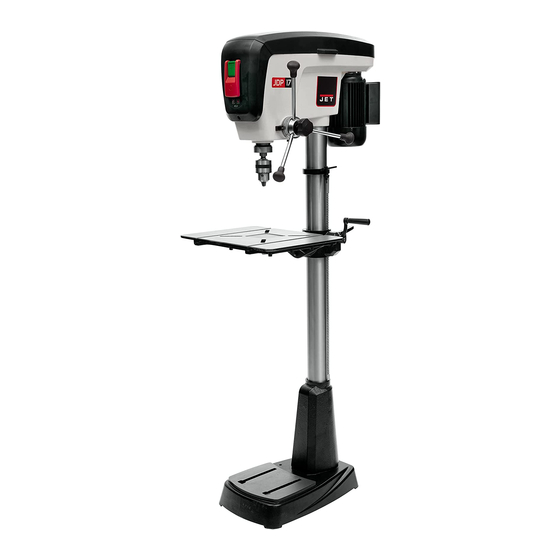
- Page 1 This .pdf document is bookmarked Operating Instructions and Parts Manual 16-speed Woodworking Drill Press Model JDP-17 427 New Sanford Road Part No. M-716300 LaVergne, Tennessee 37086 Revision B 05/2015 Ph.: 800-274-6848 ECR CN0069 www.jettools.com Copyright © 2015 JET...
-
Page 2: Warranty And Service
JET sells through distributors only. The specifications listed in JET printed materials and on official JET website are given as general information and are not binding. JET reserves the right to effect at any time, without prior notice, those alterations to parts, fittings, and accessory equipment which they may deem necessary for any reason ®... -
Page 3: Table Of Contents
13.0 Troubleshooting the JDP-17 ........................20 14.0 Replacement Parts ............................. 20 14.1.1 JDP-17 Drill Press – Exploded View ....................21 14.1.2 JDP-17 Drill Press – Parts List ......................22 15.0 Electrical Connections – JDP-17 Drill Press ....................25... -
Page 4: Safety Warnings
If removed for 5. Do not use this drill press for other than its maintenance purposes, use extreme caution intended use. If used for other purposes, JET and replace the guards immediately after disclaims any real or implied warranty and completion of maintenance. -
Page 5: About This Manual
Additional knowledge can be obtained from experienced users or trade articles. Whatever accepted methods are used, always make personal safety a priority. If there are questions or comments, please contact your local supplier or JET. JET can also be reached at our web site: www.jettools.com. -
Page 6: Specifications
5.0 Specifications Model number ............................... JDP-17 Stock number ..............................716300 Motor and electricals: Motor type ................totally enclosed fan cooled, induction, capacitor start Horsepower ............................... 3/4 HP Phase................................. single Voltage ..............................115V only Cycle ................................60Hz Listed FLA (full load amps) ..........................9 A Starting amps ............................... -
Page 7: Base Mounting Holes For Jdp-17
Figure 3: Base mounting holes The specifications in this manual were current at time of publication, but because of our policy of continuous improvement, JET reserves the right to change specifications at any time and without prior notice, without incurring obligations. -
Page 8: Setup And Assembly
6.2 Shipping contents and make certain that all items are accounted for before discarding any packing material. Report any shortages or shipping damage to your JET distributor. Exposed metal surfaces on the drill press have been factory-coated with a protectant. Remove this with a soft rag moistened with a light solvent, such ®... -
Page 9: Location
6.4 Location The drill press should be placed in a dry area, with a level floor and good lighting. Provide enough space around drill press to allow for operations and any adjustments or servicing. 6.5 Assembly Do not connect drill press to power source until machine has been fully assembled. - Page 10 Note: The locking handle (HP3) is adjustable. To reposition, pull out on the handle and rotate it, then release it, making sure it reseats itself on the bolt head. Figure 9 The head assembly is heavy! To avoid injury and/or damage to equipment, lift the head onto the column only with additional assistance! 15.
-
Page 11: Chuck Key And Wrench Storage
18. Thoroughly clean spindle, arbor and chuck (Figure 12) with a soft rag and solvent, such as The JDP-17 drill press is rated at 115V power, and comes with a plug designed for use on a circuit mineral spirits. -
Page 12: Extension Cords
Use only 3-wire extension cords that have 3-prong 8.0 Adjustments grounding plugs and 3-pole receptacles that accept the tool's plug. 8.1 Tools needed for adjustments Repair replace damaged or worn cord immediately. Pliers 2. Grounded, cord-connected tools intended for 13mm wrench use on a supply circuit having a nominal rating less 24mm wrench (provided) than 150 volts:... -
Page 13: Chuck And Arbor Removal
The alignment pin (E) only works at 90° and must 8.5 Chuck and arbor removal be reinserted when the table is returned to 90°. Reinsert the alignment pin, along with the nut, and Refer to Figure 17. tap it lightly with a rubber mallet for full insertion. 1. -
Page 14: Changing Spindle Speeds
1. Loosen lock handle (G, Figure 21). 2. Use downfeed handles (D, Figure 21) to lower the bit until it just contacts the top surface of workpiece, as shown in Figure 20. 3. Hold downfeed handle in position, and rotate scale ring (E, Figure 21) to zero. -
Page 15: Quill Retraction Lock
3. Rotate lock ring (F) counterclockwise as far as 5. Tighten lock handle (G). Depth is now set to it will turn. You should be able to feel and hear more accurate position. when the lock ring reaches the end of its rotation. -
Page 16: Led Work Light
1. Position table at the horizontal (zero degrees Turn the work light on and off with the button on on scale). the front of the drill press head. 2. Insert a small drill bit into the chuck. 3. Place a scrap board flat on the table. Do not allow board to move from this position;... -
Page 17: Safety Key
10.2 General Inspection Press button (D) to activate work light. Press again to turn light off. Before each operation of your JDP-17 drill press, Press button (E) to activate laser. Press again to make a habit of checking that all locking handles, turn off. -
Page 18: Belt Replacement
Exposed metal surfaces of table and base should 4. Slightly pull out the spring housing (D) while be kept clean and free of rust. Protective sprays or firmly holding it. DO NOT allow the spring paste wax are available from most hardware housing to turn freely in your hand, or the stores. -
Page 19: Speed Chart
12.0 Speed chart Table 2: JDP-17 recommended drill speeds (chart also located in machine hood) -
Page 20: Troubleshooting The Jdp-17
13.0 Troubleshooting the JDP-17 Table 3 Trouble Probable Cause Remedy Not connected to power. Check plug connection. Drill press will not start Fuse blown, or circuit breaker tripped. Replace fuse, or reset circuit breaker. (power light is OFF). Cord damaged. -
Page 21: Jdp-17 Drill Press - Exploded View
14.1.1 JDP-17 Drill Press – Exploded View... -
Page 22: Jdp-17 Drill Press - Parts List
14.1.2 JDP-17 Drill Press – Parts List Index No Part No Description Size 1 ....JDP17-001 ....Cap Head Columned Screw ........M8x40 ......4 2 ....JDP17-002 ....Base....................... 1 201 .... JDP17-201 ....Column Assembly (#3 thru 5) ................ 1 3 .... - Page 23 Index No Part No Description Size 48 ....JDP17-048 ....Center Pulley ....................1 49 ....JWBS14SF-418 ..Retaining Ring ............R15 ....... 1 50 ....TS-1480051 ....Hex Cap Screw ............M4x20 ......1 51 ....JDP17-051 ....Plate....................... 1 52 ....
- Page 24 120 .... JDP17-120 ....Serial Plate ....................1 121 .... JDP17-121 ....Control Label ....................1 122 .... JET-92....... Jet Logo ..............92x38mm ...... 1 123 .... JDP17-123 ....Warning Label: Laser..................1 124 .... JDP17-124 ....Motor Label ....................1 125 ....
-
Page 25: Electrical Connections - Jdp-17 Drill Press
15.0 Electrical Connections – JDP-17 Drill Press 1 Phase, 115V only... - Page 26 This page intentionally left blank.
- Page 27 This page intentionally left blank.
- Page 28 427 New Sanford Road LaVergne, Tennessee 37086 Phone: 800-274-6848 www.jettools.com...
Need help?
Do you have a question about the JDP-17 and is the answer not in the manual?
Questions and answers