Jet JMD-15 Owner's Manual
Mill/drill machine
Hide thumbs
Also See for JMD-15:
- Operator's manual (37 pages) ,
- Owner's manual (30 pages) ,
- Operating instructions and parts manual (32 pages)
Table of Contents
Advertisement
Advertisement
Table of Contents

Subscribe to Our Youtube Channel
Related Manuals for Jet JMD-15


Summary of Contents for Jet JMD-15
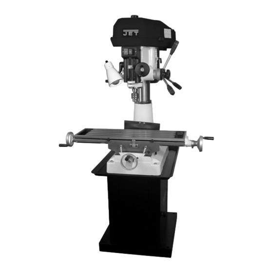
- Page 1 OWNER'S MANUAL JMD-15/18/18PFN Mill/Drill Machine (JMD-18 shown with optional CS-18 stand) WALTER MEIER (Manufacturing) Inc. 427 New Sanford Road LaVergne, Tennessee 37086 Part No. M-350020 Ph.: 800-274-6848 Revision C 04/2010 www.waltermeier.com Copyright © 2010 Walter Meier (Manufacturing) Inc.
-
Page 2: Warranty
Walter Meier is consistently adding new products to the line. For complete, up-to-date product information, check with your local Walter Meier distributor, or visit waltermeier.com. WARRANTY JET products carry a limited warranty which varies in duration based upon the product (MW = Metalworking, WW = Woodworking). WHAT IS COVERED? This warranty covers any defects in workmanship or materials subject to the exceptions stated below. -
Page 3: Warning
13. Keep children and visitors away. All visitors should be kept a safe distance from the work area. 14. Make the workshop child proof. Read and understand the entire contents of padlocks, master switches, and remove starter this manual before attempting set-up or keys. -
Page 4: Specifications
Specifications JMD-15/18/18PFN JMD-15 JMD-18 JMD-18PFN Stock No. 350017 350018 350020 Drilling Capacity 1” 1-1/4” 1-1/4” Face Mill Capacity 2-1/2” 3” 3” End Mill Capacity 1/2” 3/4” 3/4" Swing 19-3/8” 20-1/16” 20-1/16” Maximum Distance Spindle to 15” 18” 26” Table Spindle Taper Spindle Travel 3-1/2”... -
Page 5: Table Of Contents
Gib Adjustment ..........................12 Power Feed Operation ........................12 Adjusting the Spindle Return Spring ....................12 JMD-15 Parts Lists and Breakdowns ..................... 13-18 JMD-18 Parts Lists and Breakdowns ..................... 19-28 JMD-15 Wiring Diagram ........................29 JMD-18 Wiring Diagram ........................30... -
Page 6: Contents Of The Shipping Container
1/2” Drill Chuck w/ Chuck Key Adjustable Carbide Facemill Facemill Arbor Bolts, Nuts, and Washers to Attach Vise to Table 2-1/2” Angle Vise (JMD-15) 3” Angle Vise (JMD-18/18PFN) Handle Rods (JMD-15/18) Rubber Knobs (JMD-15/18) Rubber Knobs (JMD-18PFN) 3/8”x1” Hex Socket Cap Screw 3/8”... -
Page 7: Assembly
Assembly 1. Screw rubber handles (A, Fig. 1) onto handle rod (B, Fig. 1). Screw handle rod into downfeed hub (C, Fig. 1) and tighten. Flat spot on rod accommodates a combination or adjustable wrench. Note: Handle shafts are already installed into hub on JMD-18PFN. 2. -
Page 8: Lubrication
Also, press the “Off” button on the front of the machine before connecting to the power source. The JMD-15 is rated at 115/230V and comes from the factory prewired at 115V. This mill/drill comes with a plug designed for use on a circuit with an outlet that looks like (A, Fig. -
Page 9: Controls
Turn clockwise to lock. Depth Stop: JMD-15: (K, Fig. 8) located on the left side. Set nuts for desired depth stop. JMD-18: (F, Fig. 7) located in the front. Push in the button on the front of the quick adjust stop and move to desired position. -
Page 10: Changing Spindle Speeds
Motor Mount Lock Lever: (A, Fig. 9) Located on the right side of the head casting. Locks and unlocks the motor mounting plate enabling the user to tension v-belts. Head Pivot Lock: (B, Fig. 9) Located on the right rear of the head casting. Loosen two hex nuts to rotate the head 360°. -
Page 11: Arbor Replacement
4. Arrange the v-belts (A, Fig. 12) on the Note: For best results, all milling operations pulleys (B, Fig. 12) for the desired speed should be done with the quill/spindle as close to according to the speed chart (H, Fig. 11) on the head assembly as possible. -
Page 12: Gib Adjustment
Gib Adjustment 3. Rotate the spring cap clockwise to decrease After a period of time, movement of the table spring tension. Rotate the spring cap over the ways will cause normal wear. To adjust counter-clockwise to increase spring tension. the gibs for this wear: 1. -
Page 13: Jmd-15 Parts Lists And Breakdowns
JMD-15 Head Assembly... - Page 14 Parts List for the JMD-15 Mill/Drill Head Assembly Index No. Part No. Description Size 1 ....JMD15-001 ....Drawbar ..................... 1 2 ....JMD15-002A ....Spindle Lock Nut ................. 1 3 ....JMD15-003 ....Spindle Pulley ..................1 5 ....JMD15-005 ....Outer Bearing Plate................1 6 ....
- Page 15 Index No. Part No. Description Size 69-1 ..JMD15-069P1 ..Upper Belt Cover Cap ................. 1 69-2 ..JMD15-069P2 ..Upper Belt Cover Plate ................ 1 70 .... JMD15-070 ....Motor Pulley (Serial #06041349 and lower) ........... 1 ....JMD15-070N ....Motor Pulley (Serial #06041350 and higher) .......... 1 71 ....
- Page 16 210 ..TS-0570021 .....Hex Nut ............5/16”-18 ..... 1 ....JMD15-SC ....Speed Chart Label (not shown) ............1 ....JMD15-JL ....Jet Label (not shown) ................1 ....JMD15-ID ....I.D. Label (not shown) ................. 1 ....JMD15-AP ....Accessory Package (not shown) * ............1 ....
- Page 17 JMD-15 Table, Base, and Column Assembly...
- Page 18 Parts List for JMD-15 Table, Base, and Column Assembly Index No. Part No. Description Size 1 ....JMD18-201 ....Table Hand Wheel ................3 1-1 ... JMD18-201-1 ...Bolt ....................3 1-2 ... JMD18-201-2 ...Handle....................3 1-3 ... JMD18-201-3 ...Nut ..................... 3 2 ....
-
Page 19: Jmd-18 Parts Lists And Breakdowns
JMD-18/18PFN Head Assembly... - Page 20 Parts List for the JMD-18 Mill/Drill Head Assembly Index No. Part No. Description Size 1 ....JMD18N-001 ....Head Body ..................1 2 ....JMD18-001 ....Drawbar ............R8 ......1 3 ....JMD18-002A ....Spindle Lock Nut ................. 1 4 ....JMD18-003A ....Spindle Pulley ..................1 5 ....
- Page 21 Index No. Part No. Description Size 35 .... JMD18N-035A..Feed Handle Wheel Assembly .............. 1 35-1 ..JMD18N-035-1 ..Set Screw ............M8x10 ......1 37 .... JMD18-105 ....Spring Base ..................1 37-1 ..JMD18-140 ....Spring Pin ................... 2 39 .... JMD18-139 ....Round Head Screw ...........3/16”x3/4”....3 40A ..
- Page 22 119 ..JMD18-119 ....Lifting Hook ............5/16”x50mm ....1 120 ..TS-0570021 .....Hex Nut ............5/16”-18 ..... 1 ....JMD15-JL ....Jet Label (not shown) ................1 ....JMD18-ID ....I.D. Label (not shown) ................... JMD18-AP ....Accessory Package (not shown) * ............1 ....
- Page 23 JMD-18 Table, Base, and Column Assembly...
- Page 24 Parts List for the JMD-18 Mill/Drill Table, Base, and Column Assembly Index No. Part No. Description Size 601 ..JMD18-228 ....Table ...............31L ......1 602 ..JMD18-229 ....Fixed Block ..................2 603 ..JMD18-230 ....Movable Ring ..................2 604 ..TS-0207021 .....Hex Socket Head Screw ........1/4”x1/2” ....2 605 ..
- Page 25 Index No. Part No. Description Size 635-5 ..JMD18-202 Dial Clutch 635-6 ..JMD18-366 ....Pin ..............5x38......1 636 ..JMD18N-636 ....Column Base ..................1 637 ..JMD18N-637 ....Rack ..............600.5L ....... 1 638 ..JMD18-211 ....Column Cap ..................1 638-1 ..TS-0270021 .....Set Screw ............5/16”x5/16” ....1 640 ..
- Page 26 JMD-18PFN Power Feed Assembly...
- Page 27 Parts List for the JMD-18PFN Power Feed Assembly Index No. Part No. Description Size 248 ..290111 ....Main Pulley ..................1 249 ..JMD18PFN-249..Set Screw ............1/4”x3/8” ....2 ....291022AS ....Complete Gear Box Assembly ............. 1 401-1 ..291022A ....Gear Box ................... 1 401-2 ..
- Page 28 Index No. Part No. Description Size 403-1 ..2450048 ....Worm Gear Cover................1 403-2 ..JMD18PFN-346..Flat Cross Head Screw ........M4x4......3 403-3 ..JMD18PFN-320..C-Ring..............S25 ......1 403-4 ..2450024 ....Clutch Gear Case ................1 403-5 ..2450026 ....Clutch Key ..................2 403-6 ..
-
Page 29: Jmd-15 Wiring Diagram
Wiring Diagram JMD-15... -
Page 30: Jmd-18 Wiring Diagram
Wiring Diagram JMD-18 230V Only... - Page 32 WALTER MEIER (Manufacturing) Inc. 427 New Sanford Road LaVergne, Tennessee 37086 Phone: 800-274-6848 www.waltermeier.com...
Need help?
Do you have a question about the JMD-15 and is the answer not in the manual?
Questions and answers