
Related Manuals for Jet JTM-1050EVS


Summary of Contents for Jet JTM-1050EVS
- Page 1 .JET EQUIPMENT & TOOLS OPERATOR'S MANUAL JTM-1050EVS JET EQUIPMENT & TOOLS, INC. P.D.BOX 1349 253-351-6000 A WMH Company Auburn, WA 98071-1349 Fax 253-939-8001 M-690060 2/2001...
- Page 2 JET's expense, but if it is determined there is no defect, or that the defect resulted from causes not within the scope of JET's warranty, then the user must bear the cost of storing and returning the product. This warranty gives you specific legal rights, and you have other rights, which vary, from state to state.
-
Page 3: Warnings
"horse-play" are careless acts that can result in serious injury. The JTM-1050EVS mill is pre-wired from the 13. Keep visitors a safe distance from the work factory. Stock Number 690060 is Pre-wired area. -
Page 4: Table Of Contents
..28:2 The specifications in this manual are given as general information and are not binding. Jet Equipment and Tools reserve the right to effect, at any time and without prior notice, changes or alterations to parts, fittings, and accessory equipment... -
Page 5: Installation Layout
JTM-1050 EVS Installation Layout 24" 20 1/2" "--. -t:>-~ to;: "--. L__- c:::=8 5/8" Diameter Hold Down Bolt 19 3/4" 9 6 1/ 4" Fig. -
Page 6: Shipping Container Contents
Shipping Container Contents ,-----. Mill Flat Way Cover (rear) Accordion Way Cover (front) Tool Box: 1 Hex Wrench Set (1.5 - 10mm) 1 19mm Combination Wrench '.'.. 1 #2 Cross Point Screw Driver --~.",.- " 1 #2 Flat Blade Screw Driver 'W' -. -
Page 7: Lifting The Mill
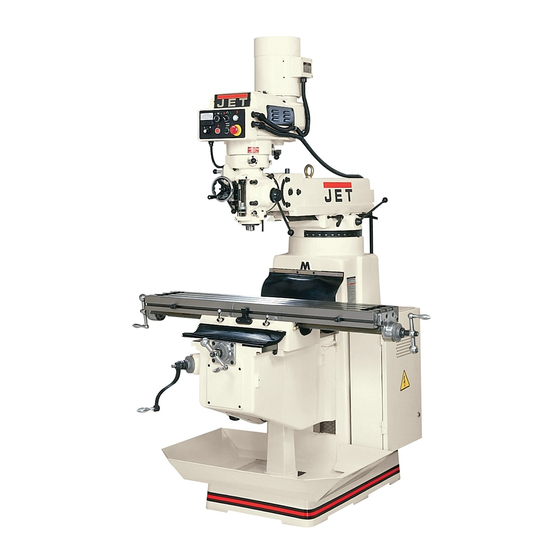
Check for level before tightening the anchor bolt nuts and after tightening them. Adjust as necessary. Note: The JTM-1050EVS pictured in figure 2 shows DRO, and POWERFEED optional accessories Fig.2 available through JET. Lubrication... -
Page 8: Electrical Connections
A qualified electrician must make all electrical connections! Failure to comply may cause serious injury! The JTM-1050EVS mill is pre-wired from the factory. Stock Number 690060 is Pre-wired 230V. Stock Number 690062 is Pre-wired 460V. This machine is not dual voltage. - Page 9 Caution Engage gently to avoid damage to the worm gear. Power feed may be engaged when spindle is rotating, however, it must be engaged gently to avoid damage to the worm gear. Do not use power feed at speeds above 3000 R.P.M It is recommended that the power feed worm gear be disengaged whenever the power feed is...
- Page 10 Caution It Is recommended thatthe handlebe leftin the neutralposition when notin use. J. Quill Stop (J, Fig. 7) - located on the front of head. Used to disengage the automatic feed in either direction as well as the setting point for working to a given depth.
-
Page 11: Operating Precautions
Operation Operating Precautions 1. Be certain the spindle brake is released before starting the motor. 2. Rotate the spindle by hand to facilitate meshing of the clutch and gears. 3. Do not use the quill power feed at speeds above 3000 RPM. -
Page 12: Setting Up For Automatic Feed
Setting Up for Automatic Feed 1. Ensure quill lock (D, Fig. 8) is off by rotating counter-clockwise. 2. Set micrometer dial (E, Fig. 8) to desired depth. 3. Engage power feed lever (A, Fig. 8) by pulling out lock knob and moving lever to the left hole. 4. - Page 13 Knee Gib Adjustment Note: when adjusting the gibs for the knee, the saddle and the table. Always start with the knee first. Adjust the saddle second, and adjust the table last. Adjust gib screws through wiper on either side of the knee where it meets the column.
-
Page 14: Parts Lists And Breakdowns
PartsListfor the JTM-1050EVSTurretMill Inverter Speed Head Assembly Index Part Size Qty. Description PVS-082 Housing TS-1503051 Hex Socket Cap Screw M6*20 PVS-087 Gear Shaft Pinion 4 ... PVS-089 Detent Plate..... PVS-090 Bearing Stop PVS-091 Spring TS-1503011 Hex Socket Cap Screw M5*14 PVS-092 Pinion Block... - Page 15 PVS-058 Brake Finger Pivot Stud 50 . PVS-099. Plastic Ball ....IVS-051 Round Head Screw IVS-052 ,.. Snap Ring S-12 PVS-052 Brake Shaft Sleeve PVS-053 Brake Lock Shaft TS-1503061 Hex Socket Cap Screw M6*25 PVS-054 Brake Lock Block TS-1540041 PVS-048 Lock Screw...
- Page 16 Inverter Speed Head Assembly...
- Page 17 Head Assembly TS-1503031 Hex Socket Cap Screw M6*12 1050B-2..Washer ... 1 1050B-3 Feed Bevel Pinion 1050B-4 Worm Gear Shaft Sleeve 1050B-5 Bushing TS-1522011 Set Screw 1050B-8 Worm Gear KEY3312 3*3*12 TS-1504031 Hex Socket Cap Screw M8*16 13 .. B-13.
- Page 18 TS-1502031 Hex Socket Cap Screw M5*12 73 . TS-1502081 Hex Socket Cap Screw M5*35 B-74 Clutch Ring Pin ""'''''''''''''''''''''''''''''''''''''''''''' B-75 Clutch Ring TS-1523021 Set Screw """""'''''''''''''''''''''''''''''''''''''''''''''' M6*8 B-78 Clutch Locknut B-79 SafetyClutchLocknut "'"'''' B-80 Overload Clutch ""'''''''''''''''''''''''''''''' B-81 Overload Clutch Sleeve ""'"'''''''''''''''''''''' KEY5813 5*8*13...
- Page 19 8-133 Nose Piece """"""""""""""""""""""""""" 8-134 Spindle Dirt Shield Angular 8earing 7207 88-7207C 8-136 Spacer 8-137 Spacer ... 88-7207C Angular 8earing 7207 139 ..8-139 ..Set Screw ..,..... 8-140 Set Screw TS-1523011 Set Screw M6*6 8-142 Quill.. 8-143 Spring Pin 3*16 8-144...
- Page 20 8-192 QuillHousing 8-193 Compression Spring 8-194 Snap Ring 8-30 8-195 8ush T8-1523011 Set Screw M6*6 8-197...
- Page 21 Head Assembly $--131 196~~ "1 ~1J\ 8""- ~"_1J\ /140 y'14!
- Page 22 BaseAssembly 1 ... 1050C-1 ...WormWasher 1050C-2 Ram Adapter 1050C-3 Adapter Scale LockNut 050C-4 1050C-6 WormGear 1050C-12 Collar 1050C-8 Worm Shaft KEY5550 ...5*5*50 1050C-10 Hook 3/4" 050C-11 C-7-1 Washer TS-1504061..Hex Socket Cap Screw M8*30 1050C-14 Spring Pin 1050C-15 Angle Plate 050C-16 Rivet 1050C-17...
- Page 23 C-80 Bearing Stop TS-1503051 Hex Socket Cap Screw M6*20 C-82 Leadscrew ....1 C-83 Handle """"""""'''''''''''''''''' C-84 Elevating Crank C-85 Gear Shear Clutch C-86 Dial Lock Nut C-87 Dial C-88 Dial Holder TS-1503051 Hex Socket Cap Screw M6*20 C-90 Bearing Stop BB-6204ZZ...
- Page 24 Base Assembly ---71 U---72 " "91 "~ (w." ,--,...
- Page 25 Leadscrew Assembly ..1/2"-20NF 0-1 . Nut..Handle ..2..0-2. .Ball Crank ..3..0-3..Oial Lock NuL ...3 0-4. .Oial... ..0-5. ..Oial Holder ..0-6 ..M6*12. 7..TS-1503031. .. Hex Socket Cap Screw. C-90 .. Bearing Stop. ..6204ZZ.. BB-6204ZZ.
- Page 26 I» (") » .j:>. C" -<...
- Page 27 One Shot Lubrication System 8 9 , CLA-8 Handle Oiler.."... "."" .'.'"'''' .ALMP-04 ... Aluminum Piece ... 13.5 Oil Regulation Distributor Oil Regulation Distributor Flexible Steel Tube 4*550 PH-4011 Elbow Joint PI-401 ..Elbow Joint ...'"...
- Page 28 Electrical P anel 1050EVS-SB1 Emergency Stop 1050EVS-SB2 Spindle Stop 1050EVS-SB3 Power Feed On 1050EVS-SA1 Fwd.-O-Rev.Spindle On 1050EVS-SA2 Pump Select Switch 1050EVS-MS Power On/Off 1050EVS-L1 Power Lamp 1050EVS-L2 Power Feed Lamp 1050EVS-TR Transformer " 1050EVS-M1 Motor Fwd. Contact Relay 1050EVS-M2 Motor Rev. Contact Relay 1050EVS-M3 Power Feed Contact Relay 1050EVS-M4...
- Page 29 Electrical Panel [Jii;] FM SD 10 2 5 4 SD PC 0° 10 9 7 ST FIsTRJ' 12 13119 R S T P PI'<U V W R S T U V W 220V, 380V, 415V, 440V Transformer 110V, L1, L2, 110V, av, 24V, 19 R 11 3 15 R 11 3 15 R 11 3 14 U V W R S T...
- Page 30 AC 31'J 230V/460V ..Q) ns D..(5 .!!! =: CD ::I ACM~ AFM,10 z"5 ..c: +10V . l- -, ,. > C) -0 :1-- (.) CD .f!.q- Q) 'U ..c: -"" > > - ..'UD.. ~ .!!! .- N :I: CD L____..J L__---.J...
- Page 31 BRAKE-L,S 0> M2*. '" ',J... / POWER-FEED COOLANT DOOR-L,S POWER- PUMP LAMP...
Need help?
Do you have a question about the JTM-1050EVS and is the answer not in the manual?
Questions and answers