
Related Manuals for Jet JTM-1050


Summary of Contents for Jet JTM-1050
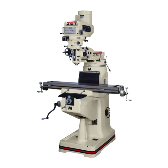
- Page 1 .JET EQUIPMENT & TOOLS OPERATOR'S MANUAL JTM-1050 Turret Mill JET EQUIPMENT & TOOLS, INC. P.O.BOX 1349 253-351-6000 A WMH Company Auburn, WA 98071-1349 Fax 253-939-8001 M-690050 5/98...
-
Page 2: Important Information
LIMITED TOOL AND EQUIPMENT WARRANTY JET makes every effort to assure that its products meet high quality and durability standards and warrants to the original retail consumer/purchaser of our products that each product be free from defects in materials and workmanship as follows: 1 YEAR LIMITED WARRANTY ON THIS JET PRODUCT. -
Page 3: Warnings
Lt WARNING Read and understand the entire Giveyour workundividedattention. Looking instruction manual before attempting set- around,carryingon a conversation, a nd up or operation of this machine. "horse-play" a re carelessactsthatcan result in serious injury. Always wear approved safety glasses/face Keepvisitorsa safedistancefromthe work shields while using this machine. -
Page 4: Table Of Contents
13-27 Electrical Schematic The specifications in this manual are given as general information and are not binding. JET Equipment and Tools reserves the right to effect. at any time and without prior notice, changes or alterations to parts. fittings, and accessory equipment deemed necessary for any reason whatsoever. -
Page 5: Installation Layout
JTM-1050 Installation Layout 24" 20 1/2" "'- lO;: "'- - --, ,-,. ,!:b::J. L__- ---1 5/8" Diameter Hold Down Bolt 19 3/4" 96 1/4" Fi 9 . -
Page 6: Shipping Container Contents
Shipping Container Contents Mill Flat Way Cover (rear) Accordion Way Cover (front) Tool Box: 1 Hex Wrench Set (1.5 -10mm) 1 19mm Combination Wrench 1 #2 Cross Point Screw Driver 1 #2 Flat Blade Screw Driver 1 Plastic Oil Can 1 Operator's Manual 1 V\!arrantyCard 1 Eye Bolt... -
Page 7: Lubrication
Tighten ram locking bolts (A, Fig. 2) before lifting. .JET Carefully lift the mill and move to a position over the "11'1'" anchor bolts. Lower the mill over the anchor bolts, "~A... -
Page 8: Electrical Connections
Electrical Connections WARNING All electrical connections must be made by a qualified electrician! Failure to comply may cause serious injury! The JTM-1 050 mill is rated at 230/460V and comes from the factory prewired at 230V. Confirm power at the site matches power requirements of the mill before connecting to the power source. - Page 9 D. High-Neutral-Low Lever (D, Fig. 5) - located on the right side of the head. Upper position is high speed (direct drive). Middle position is neutral. Lower position is low speed (back gear). Caution Do not shift High-Low Gear while motor is running.
-
Page 10: Operating Precautions
with micrometer adjusting nut (forcing feed control lever to drop out automatically),or until lever is released manually by engaging lever to the right. Manual Feed (J, Fig. 6) - located on the left side of the head. Feed reversing knob (K, Fig. 6) must be in the neutral position. -
Page 11: Changing Speed Range
Rotate the spindle by hand to facilitate meshing of the clutch and gears. Do not use the quill power feed at speeds above 3000 RPM. It is recommended that the power feed worm gear be disengaged whenever the power feed is not required. -
Page 12: Setting Up For Automatic Feed
Setting Up for Automatic Feed Ensure quill lock (0, Fig. 8) is off by rotating counter-clockwise. Set micrometer dial (E, Fig. 8) to desired depth. Engage auto quill feed lever (A, Fig. 8) by pulling out lock knob and moving lever to the left hole. Select feed rate (F, Fig. - Page 13 Table Adjustment Adjust gib screws found on the sides of the table toward the front of the carriage. Head Alignment The scale on the ram adapter and for head rotation (Fig. 10) are guides only. Close tolerance work will require the use of a dial indicator to make sure the head is 90°...
-
Page 14: Parts Lists And Breakdowns
114. - Page 15 Parts List for the JTM-1050Turret Mill Variable Speed Head Assembly Index Part Size Description Qty. .PVS-001 Housing PVS-002 Motor Pulley TS-1523011 '''''''''''''''''''''' Set Screw M6*6 .PVS-004 """"""""""""'" Belt 3830900 PVS-005 Motor Pulley KEY7725 7*7*25 PVS-008 Motor Pulley Spring PVS-D09""'"'''''''''''''''''''' Spring Stop Washer PVS-011 """"""""""""'"...
- Page 16 Braka ..PVS-047 Lining ...1 PVS-048 ... Lock Screw .PVS-049 .. Brake Spring PVS-050 Lower Housing Cover TS-1503051 Hex Socket Cap Screw M6*20 PVS-052 Brake Shaft Sleeve PVS-053 Brake Lock Shaft PVS-054 ,... Brake Lock Block TS-1503061 Hex Socket Cap Screw M6*25 PVS-056 Snap Ring...
- Page 17 106 ..PVS-1 06 Snap Ring '''''''''''''''''''''''''''''''''''''''''' S-28 Lock Washer PVS-1 09 TS1540041 TS-0209051 Hex Socket Cap Screw 3/8"*1" PVS-112 """"""""""""'" Motor '"'''''''''''''''''''''''''''''''''''''''''''''''''''''' """"'"'''''''' 1/8"*1 / 4" .PVS-113 Round Head Screw. '''''''''''''''''''''''''''''' '''''''''' "'" .PVS-114 Draw Bar PVS-115 Draw Bar Washer Hex Socket CapScrew M5*6 PVS-118 ""'"''''''''''''''''''''...
- Page 18 Head Assembly " j."- ~_131 195 ~ 196~@-129 _142 ~135 8--13, ~_135 V'41 Q-133...
- Page 19 Head Assembly TS-1503031 Hex Socket Cap Screw M6*12 Washer Feed Bevel Pinion Worm Gear Shaft Sleeve .B-5 Bushing TS-1522011 Set Screw 8 ., Worm Gear KEY3312 3*3*12 TS-1504031 Hex Socket Cap Screw M8*16 B-13... Washer KEY3308 Key.. " 3*3*8 B-15 Bevel Gear "'''''''''''''''''''''''''''''''' B-16...
- Page 20 TS-1502031 Hex Socket Cap Screw M5*12 .TS-1502081 Hex Socket Cap Screw M5*35 8-74 Clutch Ring Pin... 8-75 Clutch Ring TS-1523021 Set Screw M6*8 ...8-78 Clutch Locknut 8-79 ..., Safety Clutch Locknut 8-80 Overload Clutch 8-81 OverloadClutchSleeve .KEY5813 5*8*13 8-83 ,.. Hex Socket Head 8olt .TS-1523011 Set Screw M6*6...
- Page 21 .B-132 """"'" B-133 Nose Piece B-134 Spindle Dirt Shield 135 ..:...BB-7207C . Angular Bearing 7207.. B-136 Spacer B-137"""""'" Spacer BB-7207C Angular Bearing '"'''''''''''''''''''''''''''''''''''''''''' 7207 B-139 Set Screw B-14O Set Screw .TS-1523011.., Set Screw M6*6 B-142 " Quill ""'''''''''''''''''''''''''''''''''''''''''''''''''''''''''''' ..B-143 Spring Pin 3*16 ..B-144 Set Screw...
- Page 22 Plastic Ball B-191 Black Housing 192 ...,.. B-192 Quill B-193 Compression Spring B-194 SnapRing S-30 B-195 Bush TS-1523011 Set Screw M6*6 B-197"",""""""""""""'"...
- Page 23 Base Assembly "" /191 I / 95 '-"9-,...
- Page 24 Base Assembly Worm Washer ...C-2 Ram Adaptor...'"'''''''''''''''''''''''' Adaptor Scale Lock Nut ". C-6... Worm Gear """'" "'"'''''' C-12 ....Collar .C-8 Worm Shaft ...1 ..KEY5550 5*5*50 C-10 C-11 Hook 3/4" 12 .. C-7-1 Washer "'"'''''''' TS-1504061 Hex Socket Cap Screw M8*30 C-14 Spring Pin...
- Page 25 C-80 Bearing Stop TS-1503051 Hex Socket Cap Screw M6*20 C-82 Leadscrew """"""""""""""""""""""""""" C-83 Handle 84 .""'" C-84 Elevating Crank C-85 Gear Shear Clutch """" C-86 Dial Lock Nut '"'''''''''''''''''''''''''''''''''''' C-87 Dial """"'''''''''''''''''''''''''' C-88 Dial Holder TS-1503051 Hex Socket Cap Screw M6*20 C-90 Bearing Stop...
- Page 26 (]'I ""'( » 0"' '<...
- Page 27 leadscrew Assembly 0-1. ..,"" ,..1/2»-20NF "'" 0-2. Handle .0-3 Ball Crank 4 ..0-4 ..,.., ,... Dial Lock Nut..3 Dial 6 .. Dial Holder..TS-1503031 '"'''''' Hex Socket Cap Screw M6*12 C-90 Bearing Stop 3" ...BB-6204ZZ Ball Bearing 6204ZZ 0-10...
- Page 28 8 9 , One Shot Lubrication System CLA-8 ...-..Handle Oiler ALMP-04 Aluminum Piece 13.5mm.., Oil Regulation Distributor ..A-4 Oil Regulation Distributor .A-5 '.""'''''' Flexible Steel Tube 4*550 PH-4011 ElbowJoint PI-401 Elbow Joint ,..PA-4 Thimble Nut PB-4 Thimble PG-004 Union .JTM4VS-BUTW1458 Screw...
-
Page 29: Electrical Schematic
Electrical Sche,matic For 4 60 V For 230 Power Power Switch Motor...
Need help?
Do you have a question about the JTM-1050 and is the answer not in the manual?
Questions and answers