Table of Contents
Advertisement
Quick Links
This .pdf document is bookmarked
Operating Instructions and Parts Manual
Variable Speed Mill-Drill Machines
Models: JMD-45VSPF, JMD-45VSPFT
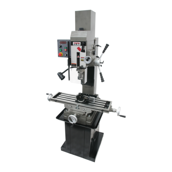
JMD-45VSPFT (tapping model) shown
JET
427 New Sanford Road
LaVergne, Tennessee 37086
Part No. M-351050
Ph.: 800-274-6848
Edition 1 04/2017
www.jettools.com
Copyright © 2017 JET
1
Advertisement
Table of Contents

Related Manuals for Jet JMD-45VSPF


Summary of Contents for Jet JMD-45VSPF
- Page 1 This .pdf document is bookmarked Operating Instructions and Parts Manual Variable Speed Mill-Drill Machines Models: JMD-45VSPF, JMD-45VSPFT JMD-45VSPFT (tapping model) shown 427 New Sanford Road LaVergne, Tennessee 37086 Part No. M-351050 Ph.: 800-274-6848 Edition 1 04/2017 www.jettools.com Copyright © 2017 JET...
-
Page 2: Important Safety Instructions
A guard or other part that is Do not use this mill-drill for other than its damaged should be properly repaired or intended use. If used for other purposes, JET replaced. disclaims any real or implied warranty and holds itself harmless from any injury that may result 17. -
Page 3: Switch Lock-Out
26. Maintain tools with care. Keep cutters sharp 33. Don’t use in dangerous environment. Don’t use and clean for the best and safest performance. power tools in damp or wet location, or expose Follow instructions for lubricating and changing them to rain. Keep work area well lighted. accessories. -
Page 4: Table Of Contents
11.0 Optional accessory ............................. 17 12.0 Replacement Parts ............................. 17 12.1.1 JMD-45VSPF, -45VSPFT Table and Base Assembly – Exploded View ..........18 12.1.2 JMD-45VSPF, -45VSPFT Table and Base Assembly – Parts List ............19 12.2.1 JMD-45VSPF, -45VSPFT Column Assembly – Exploded View ............21 12.2.2 JMD-45VSPF, -45VSPFT Column Assembly –... -
Page 5: About This Manual
Whatever accepted methods or materials are used, always make personal safety a priority. If there are questions or comments, please contact your local supplier or JET. JET can also be reached at our web site: www.jettools.com. -
Page 6: Specifications
4.0 Specifications Table 1 Model number JMD-45VSPF JMD-45VSPFT Stock number 351050 351051 Motor and Electricals Motor type Totally-enclosed, fan-cooled, induction Horsepower 1.5 HP (1.1 kW) Motor Phase Motor Voltage 230V Input Voltage single phase, 115V or 230V (prewired for 115V) -
Page 7: Mounting Hole Centers
= not applicable The specifications in this manual were current at time of publication, but because of our policy of continuous improvement, JET reserves the right to change specifications at any time and without prior notice, without incurring obligations. -
Page 8: Setup And Assembly
(See Figure 4-1 for mounting hole spacing.) Check for level again. Adjust as necessary until mill-drill is level after fastening hardware has been tightened. NOTE: An optional stand is available from JET, see sect. 11.0. 5.5 Assembly See Figure 5-1 to identify parts. -
Page 9: Lubrication
Loosen lock handles (R, Figure 7-2) and raise grounded. Failure to comply may cause serious head by turning crank (E) clockwise to remove or fatal injury. shipping block from table. Use only 3-wire extension cords that have 3-prong grounding plugs and 3-pole receptacles that accept 5.6 Lubrication the tool's plug. -
Page 10: Voltage Conversion
If the tool must be reconnected for use on a different Table 2 shows recommended size to use depending type of electric circuit, the reconnection should be on cord length and nameplate ampere rating. If in made by qualified service personnel; and after doubt, use the next heavier gauge. -
Page 11: Head Adjustments
Grasp arbor with one hand while loosening The scales can be adjusted by loosening screw (T drawbar with the other. Continue to loosen and rotating scale to align with indicator. drawbar until arbor can be withdrawn from The stops (T ) can be adjusted to any point along spindle. -
Page 12: Operation
Rotate spring cap clockwise to decrease spring tension; counterclockwise to increase. Tighten knob (A). Figure 8-1: operating controls (tapping model 45VSPFT shown) Figure 7-4: spindle return spring adjustment 8.0 Operation 8.1 Operating controls Refer to Figures 8-1 and 8-2. Depth stop and scale. All models: Turn scale ring (A ) until desired depth on scale aligns with indicator. -
Page 13: Powerfeed Operation
8.4 Manual fine feed Emergency stop (M). Push to stop all machine functions. To restart, rotate E-stop button clockwise See Figures 8-1 and 8-2: until it disengages. Note: It is recommended that start/stop button (N) be used for normal spindle Turn off machine –... -
Page 14: User-Maintenance
9.1 General maintenance Turn off machine – spindle stopped. Adjust depth stop to highest position. After each use, wipe down machine with a clean rag and apply light coat of oil to exposed metal Engage fine feed handwheel, and turn it to set surfaces. -
Page 15: Lubrication
9.3 Lubrication Note: Spindle bearings are sealed and do not require further lubrication. Recommended lubricant Location (see Figure 13-1) Frequency (an equivalent may be used) ® Ball oiler, handwheels (L Mobil DTE Oil Heavy Medium Once daily ® Ball oiler, front of table (L Mobil DTE Oil Heavy Medium Once daily... -
Page 16: Troubleshooting Jmd-45Vs Series Mill-Drills
10.0 Troubleshooting JMD-45VS series Mill-Drills Table 5 Symptom Possible Cause Correction* Motor will not start. Low voltage. Check power line for proper voltage. Open circuit in motor or loose Inspect all lead connections on motor for connection. loose or open connections. Switch failure. -
Page 17: Optional Accessory
12.0 Replacement Parts An optional enclosed stand (p/n 350045) is available Replacement parts are listed on the following for your JET Mill-Drill Machine. Contact your dealer pages. To order parts or reach our service or visit our website for more information. -
Page 18: Jmd-45Vspf, -45Vspft Table And Base Assembly - Exploded View
12.1.1 JMD-45VSPF, -45VSPFT Table and Base Assembly – Exploded View... -
Page 19: Jmd-45Vspf, -45Vspft Table And Base Assembly - Parts List
12.1.2 JMD-45VSPF, -45VSPFT Table and Base Assembly – Parts List Index No. Part No. Description Size 601 .... JMD18-228G ..... Table ................ 31L ........ 1 602 .... JMD18-229 ....Fixed T-Block ....................2 603 .... JMD18-230 ....Stop Ring ....................... 2 604 .... - Page 20 * Contents of Accessory Package: ....JMD18-020 ....Cutter Arbor ....................1 ....JMD18-022 ....Handle ......................4 ....JMD18-039 ....Handle Rod ....................3 ....JMD18-040 ....Knob ......................3 ....JMD18-050 ....Lock Handle ....................1 ....
-
Page 21: Jmd-45Vspf, -45Vspft Column Assembly - Exploded View
12.2.1 JMD-45VSPF, -45VSPFT Column Assembly – Exploded View... -
Page 22: Jmd-45Vspf, -45Vspft Column Assembly - Parts List
12.2.2 JMD-45VSPF, -45VSPFT Column Assembly – Parts List Index No. Part No. Description Size 501 .... JMD45GH-501 ..Vertical Square Column ................. 1 502 .... JMD45GH-502 ..Headstock Swivel Base ................. 1 503 .... JMD45GH-503 ..Oil Cup ..............PT1/8" ......2 504 .... -
Page 23: Jmd-45Vspf, -45Vspft Gear Head Assembly - Exploded View
12.3.1 JMD-45VSPF, -45VSPFT Gear Head Assembly – Exploded View... -
Page 24: Jmd-45Vspf, -45Vspft Gear Head Assembly - Parts List
52 ....TS-0071141 ....Hex Cap Screw ............5/8”-11 x 5-1/2” ..... 2 53 ....GHD20-53 ....Oil Plug ..............1/4”PT ......1 55 ..... JMD45VSPF-55 ..Electric Box Complete (JMD-45VSPF) ............ 1 ....JMD45VSPFT-55 ..Electric Box Complete (JMD-45VSPFT) ..........1 65 ..... - Page 25 345 .... TS-0640081 ....Hex Nut ..............5/16”-18 ......1 346 .... GHD20PF-346 ..Manual Feed Knob ..................1 347 .... JMD45VSPF-347 ..Name Plate for JMD-45VSPF ................ 1 ....JET-92 ....... JET Logo (not shown) ..........92x38MM ...... 1...
- Page 26 379 .... GHD20PF-379 ..Double Rd. Hd. Key ..........5 x 5 x 28L mm ..... 1 380 .... GHD20PF-380 ..C-Ring......................1 381 .... 2450088A ....Graduated Bottom Plate ................1 ....LM000292 ....ID/Warning Label, JMD-45VSPF (not shown) ..........1 ....LM000293 ....ID/Warning Label, JMD-45VSPFT (not shown) ..........1...
-
Page 27: Jmd-45Vspft Tapping Assembly - Exploded View
16 ....6192 ......Depth Stop Block ................... 1 34 ....JMD45VSPFT-34 ..Name Plate for JMD-45VSPFT ..............1 ....JET-92 ....... JET Logo (not shown) ..........92x38MM ...... 1 70 ....61102 ......Limit Plate ...................... 1 71 .... -
Page 28: Jmd-45Vspf, -45Vspft Gears Assembly - Exploded View
12.5.1 JMD-45VSPF, -45VSPFT Gears Assembly – Exploded View... -
Page 29: Jmd-45Vspf, -45Vspft Gears Assembly - Exploded View
12.5.2 JMD-45VSPF, -45VSPFT Gears Assembly – Exploded View Index No. Part No. Description Size 1 ....JMD45VSPF-100 ..Main Shaft Cover ................... 1 2 ....GHD20-28 ....Oil Seal ......................1 3 ....JMD45GH-03 .... Draw Bar ..............7/16” ......1 4 .... -
Page 30: Jmd-45Vspf Electric Box Assembly - Exploded View
12.6.1 JMD-45VSPF Electric Box Assembly – Exploded View... -
Page 31: Jmd-45Vspf Electric Box Assembly - Parts List
55-36 ..JMD45VSPF-55-36 ... Sensor ......................1 55-37 ..JSH275-43-1 ..... Phillips Pan Head Machine Screw ......M3x16L ......2 55-38 ..JMD45VSPF-55-38 ... Control Panel for JMD-45VSPF ..............1 55-39 ..JMD45VSPF-55-39 ... Fuse Bracket....................1 55-40 .. -
Page 32: Jmd-45Vspft Electric Box Assembly - Exploded View
12.7.1 JMD-45VSPFT Electric Box Assembly – Exploded View... -
Page 33: Jmd-45Vspft Electric Box Assembly - Parts List
12.7.2 JMD-45VSPFT Electric Box Assembly – Parts List Index No. Part No. Description Size ....JMD45VSPFT-55 ..Electric Box Complete (JMD-45VSPFT) ..........1 55-1 ... JMD45VSPF-55-1 ..Electric Box ....................1 55-2 ... JMD45VSPFT-55-2 ... Front Cover ....................1 55-3 ... -
Page 34: Electrical Connections, Jmd-45Vspf Series
13.0 Electrical Connections, JMD-45VSPF series 13.1 Wiring Diagram for JMD-45VSPF... -
Page 35: Wiring Diagram For Jmd-45Vspft
13.2 Wiring Diagram for JMD-45VSPFT... -
Page 36: Warranty And Service
JET sells through distributors only. The specifications listed in JET printed materials and on official JET website are given as general information and are not binding. JET reserves the right to effect at any time, without prior notice, those alterations to parts, fittings, and accessory equipment which they may deem necessary for any reason ®... - Page 37 This page intentionally left blank.
- Page 38 This page intentionally left blank.
- Page 39 This page intentionally left blank.
- Page 40 427 New Sanford Road LaVergne, Tennessee 37086 Phone: 800-274-6848 www.jettools.com...
Need help?
Do you have a question about the JMD-45VSPF and is the answer not in the manual?
Questions and answers