Jet JMD-15 Operating Instructions And Parts Manual
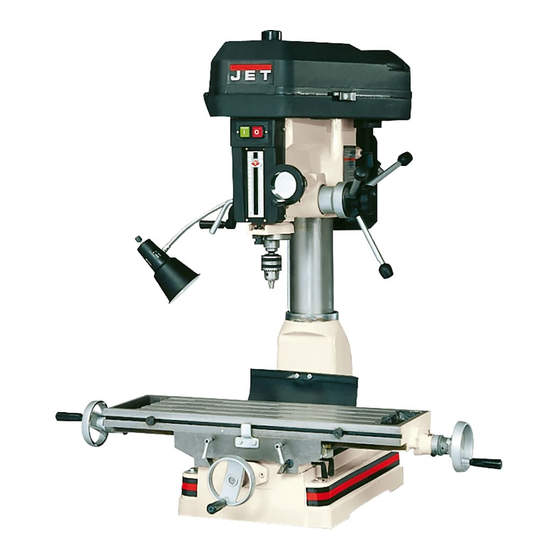
Mill/drill machine
Hide thumbs
Also See for JMD-15:
- Operator's manual (37 pages) ,
- Owner's manual (30 pages) ,
- Owner's manual (32 pages)
Table of Contents
Advertisement
Advertisement
Table of Contents

Subscribe to Our Youtube Channel
Related Manuals for Jet JMD-15


Summary of Contents for Jet JMD-15
- Page 1 This .pdf document is bookmarked Operating Instructions and Parts Manual JMD-15/18/18PFN Mill/Drill Machine (JMD-18 shown with optional CS-18 stand) 427 New Sanford Road LaVergne, Tennessee 37086 Part No. M-350020 Ph.: 800-274-6848 Revision F1 03/2014 www.jettools.com Copyright © 2014 JET...
-
Page 2: Warranty And Service
JET sells through distributors only. The specifications listed in JET printed materials and on official JET website are given as general information and are not binding. JET reserves the right to effect at any time, without prior notice, those alterations to parts, fittings, and accessory equipment which they may deem necessary for any reason ®... -
Page 3: Table Of Contents
13.1.1 JMD-15 Head Assembly – Exploded View ..................13 13.1.2 JMD-15 Head Assembly – Parts List ....................14 13.2.1 JMD-15 Table, Base, and Column Assembly – Exploded View ............17 13.2.2 JMD-15 Table, Base, and Column Assembly – Parts List ..............17 ... -
Page 4: Warnings
13. Keep children and visitors away. All visitors should be kept a safe distance from the work area. 14. Make the workshop child proof. 3.0 Warnings padlocks, master switches, and remove starter keys. Read and understand the entire contents of 15. -
Page 5: Specifications
760 lbs. 800 lbs. The specifications in this manual are given as general information and are not binding. JET reserves the right to effect, at any time and without prior notice, changes or alterations to parts, fittings, and accessory equipment deemed necessary for any reason whatsoever. -
Page 6: Contents Of Shipping Container
1/2” Drill Chuck w/ Chuck Key Adjustable Carbide Facemill Facemill Arbor Bolts, Nuts, and Washers to Attach Vise to Table 2-1/2” Angle Vise (JMD-15) 3” Angle Vise (JMD-18/18PFN) Handle Rods (JMD-15/18) Rubber Knobs (JMD-15/18) Rubber Knobs (JMD-18PFN) 3/8”x1” Hex Socket Cap Screw 3/8”... -
Page 7: Assembly
7.0 Assembly 1. Screw rubber handles (A, Fig. 1) onto handle rod (B, Fig. 1). Screw handle rod into downfeed hub (C, Fig. 1) and tighten. Flat spot accommodates combination or adjustable wrench. Note: Handle shafts are already installed into hub on JMD-18PFN. -
Page 8: Lubrication
9.0 Lubrication Lubricate ball oilers (A, Fig. 4) by the X/Y-axis hand wheels, the oiler at the raising/lowering crank handle, and the oiler on front of the bed once daily with Mobil DTE® Oil Heavy Medium. Lubricate the ways (B, Fig. 4) once daily with Mobil DTE®... -
Page 9: Controls
Turn clockwise to lock. Depth Stop: JMD-15: (K, Fig. 8) located on the left side. Set nuts for desired depth stop. JMD-18: (F, Fig. 7) located in the front. Push in the button on the front of the quick adjust stop and move to desired position. -
Page 10: Adjustments
3. Release two latches (G, Fig. 11) on belt Motor Mount Lock Lever: (A, Fig. 9) cover and slide pulley guard open (I, Fig. 11). Located on the right side of the head casting. Locks and unlocks the motor mounting plate enabling the user to tension v-belts. -
Page 11: Arbor Replacement
4. Arrange the v-belts (A, Fig. 12) on the pulleys (B, Fig. 12) for the desired speed according to the speed chart (H, Fig. 11) on the belt cover. 5. Tension the v-belts by pushing the motor away from the head casting and locking the motor mount lock lever (F, Fig. -
Page 12: Gib Adjustment
3. Rotate the spring cap clockwise to decrease 12.3 Gib Adjustment spring tension. Rotate the spring cap counter-clockwise increase spring After a period of time, movement of the table tension. over the ways will cause normal wear. To adjust the gibs for this wear: 1. -
Page 13: Replacement Parts
13.0 Replacement Parts 13.1.1 JMD-15 Head Assembly – Exploded View... -
Page 14: Jmd-15 Head Assembly - Parts List
13.1.2 JMD-15 Head Assembly – Parts List Index No. Part No. Description Size 1 ....JMD15-001 ....Drawbar ....................1 2 ....JMD15-002A ....Spindle Lock Nut ................... 1 3 ....JMD15-003 ....Spindle Pulley..................1 5 ....JMD15-005 ....Outer Bearing Plate ................1 6 .... - Page 15 Index No. Part No. Description Size 71 ..... VB-A30 ....V-Belt ..............A30 ......1 72 ..... BB-6204Z ....Ball Bearing ............6204Z ......2 73 ..... JMD15-073 ....Inter Pulley .................... 1 74 ..... VB-A38 ....V-Belt ..............A38 ......1 75 ..... JMD15-075P ....Inter Pulley Shaft ................... 1 76 .....
- Page 16 211-10 ..JMD18-125-7 ...Hex. Socket Headless Screw ......M5x10L ...... 1 ....JMD15-SC ....Speed Chart Label (not shown) ............. 1 ....JMD15-JL ....Jet Label (not shown) ................1 ....JMD15-ID ....I.D. Label (not shown)................1 ....JMD15-AP ....Accessory Package (not shown) * ............1 ....
-
Page 17: Jmd-15 Table, Base, And Column Assembly - Exploded View
13.2.1 JMD-15 Table, Base, and Column Assembly – Exploded View... -
Page 18: Jmd-15 Table, Base, And Column Assembly - Parts List
13.2.2 JMD-15 Table, Base, and Column Assembly – Parts List Index No. Part No. Description Size 1 ....JMD18-201 ....Table Hand Wheel ................. 3 1-1.... JMD18-201-1 ...Bolt......................3 1-2.... JMD18-201-2 ...Handle....................3 1-3.... JMD18-201-3 ...Nut ......................3 2 ....JMD18-202 ....Dial Clutch ..................... 2 2-1.... -
Page 19: Jmd-18/18Pfn Head Assembly - Exploded View
13.3.1 JMD-18/18PFN Head Assembly – Exploded View... -
Page 20: Jmd-18/18Pfn Head Assembly - Parts List
13.3.2 JMD-18/18PFN Head Assembly – Parts List Index No. Part No. Description Size 1 ....JMD18N-001 ....Head Body .................... 1 2 ....JMD18-001 ....Drawbar .............R8 ......1 3 ....JMD18-002A ....Spindle Lock Nut ................... 1 4 ....JMD18-003A ....Spindle Pulley..................1 5 .... - Page 21 Index No. Part No. Description Size 37 ..... JMD18-105 ....Spring Base ................... 1 37-1 ..JMD18-140 ....Spring Pin....................2 39 ..... JMD18-139 ....Round Head Screw ..........3/16”x3/4” ....3 40A ..JMD18-103A ....Spring Cover Assembly ................. 1 40-1 ..JMD18-103 ....Spring Cover ..................1 40-2 ..
- Page 22 125-6 ..JMD18-125-6 ...Hex Socket Head Screw ........M5x15L ...... 2 125-7 ..JMD18-125-7 ...Hex. Socket Headless Screw ......M5x10L ...... 1 ....JMD15-JL ....Jet Label (not shown) ................1 ....JMD18-ID ....I.D. Label (not shown)....................JMD18-303 ....Thermal Relay (not shown) .........15A, 220V ....1 ....
- Page 23 * Contents of the Accessory Package: ....JMD18-020 ....Cutter Arbor ................... 1 ....JMD18-022 ....Handle....................4 ....JMD18-039 ....Handle Rod ................... 3 ....JMD18-040 ....Knob ..................... 3 ....JMD18-050 ....Lock Handle ..................1 ....561704 ....Drill Chuck w/Chuck Key................ 1 ....
-
Page 24: Jmd-18 Table, Base, And Column Assembly - Exploded View
13.4.1 JMD-18 Table, Base, and Column Assembly – Exploded View... -
Page 25: Jmd-18 Table, Base, And Column Assembly - Parts List
13.4.2 JMD-18 Table, Base, and Column Assembly – Parts List Index No. Part No. Description Size 601 ... JMD18-228 ....Table ..............31L ......1 602 ... JMD18-229 ....Fixed Block .................... 2 603 ... JMD18-230 ....Movable Ring ..................2 604 ... TS-0207021 .....Hex Socket Head Screw ........1/4”x1/2” ..... 2 605 ... - Page 26 Index No. Part No. Description Size 638-1 ..TS-0270021 .....Set Screw ............5/16”x5/16” ....1 640 ... JMD18-209 ....Column Flange Ring ................1 641 ... JMD18-641 ....Hex Socket Cap Bolt...........5/8”x2-1/2” ....5 642 ... TS-0720131 .....Lock Washer ............5/8”......5 643 ... TS-0208022 .....Hex Socket Head Screw ........5/16”x1/2” ....2 644 ...
-
Page 27: Jmd-18Pfn Power Feed Assembly - Exploded View
13.5.1 JMD-18PFN Power Feed Assembly – Exploded View... -
Page 28: Jmd-18Pfn Power Feed Assembly - Parts List
13.5.2 JMD-18PFN Power Feed Assembly – Parts List Index No. Part No. Description Size 248 ... 290111 ....Main Pulley .................... 1 249 ... JMD18PFN-249 ..Set Screw ............1/4”x3/8” ..... 2 ....291022AS ....Complete Gear Box Assembly ............... 1 401-1 ..291022A ....Gear Box ....................1 401-2 .. - Page 29 Index No. Part No. Description Size 403-7 ..2450028....Spring....................2 403-8 ..2450027....Spring Pin....................2 403-9 ..2450023....Worm Gear .................... 1 403-10 ..2450022....Key......................2 403-11 ..291029A ....Pinion Shaft ................... 1 404 ... JMD18PFN-250 ..Flat Head Screw ..........3/16”x3/8” ....1 405 ...
-
Page 30: Electrical Connections
14.0 Electrical Connections 14.1 Wiring Diagram: JMD-15 Only... -
Page 31: Wiring Diagram: Jmd-18 Only
14.2 Wiring Diagram: JMD-18 Only... - Page 32 427 New Sanford Road LaVergne, Tennessee 37086 Phone: 800-274-6848 www.jettools.com...
Need help?
Do you have a question about the JMD-15 and is the answer not in the manual?
Questions and answers