Table of Contents
Advertisement
This .pdf document is bookmarked
Operating Instructions and Parts Manual
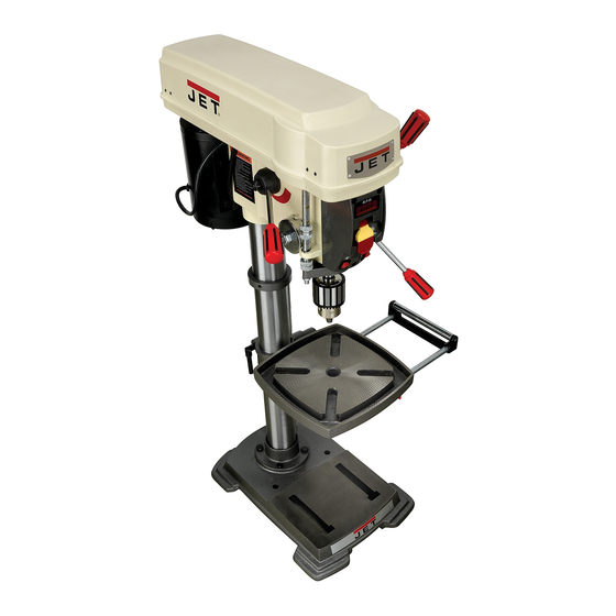
12" Variable Speed Drill Press
Model: JDP-12
WALTER MEIER (Manufacturing) Inc.
427 New Sanford Road
LaVergne, Tennessee 37086
Part No. M-707300
Ph.: 800-274-6848
Revision A2 03/2012
www.waltermeier.com
Copyright © 2012 Walter Meier (Manufacturing) Inc.
Advertisement
Table of Contents

Related Manuals for Jet JDP-12


Summary of Contents for Jet JDP-12
- Page 1 This .pdf document is bookmarked Operating Instructions and Parts Manual 12" Variable Speed Drill Press Model: JDP-12 WALTER MEIER (Manufacturing) Inc. 427 New Sanford Road LaVergne, Tennessee 37086 Part No. M-707300 Ph.: 800-274-6848 Revision A2 03/2012 www.waltermeier.com Copyright © 2012 Walter Meier (Manufacturing) Inc.
-
Page 2: Warranty And Service
Walter Meier is consistently adding new products to the line. For complete, up-to-date product information, check with your local Walter Meier distributor, or visit waltermeier.com. WARRANTY JET products carry a limited warranty which varies in duration based upon the product (MW stands for Metalworking, WW stands for Woodworking). WHAT IS COVERED? This warranty covers any defects in workmanship or materials subject to the exceptions stated below. -
Page 3: Table Of Contents
Table of Contents Warranty and Service ............................2 Table of Contents ..............................3 Warnings ................................4 Introduction ................................6 Specifications ..............................6 Unpacking ................................7 Contents of the Shipping Container ........................7 Hardware ................................. 7 Assembly ................................8 Base and Column Assembly ..........................8 Table and Rack .............................. -
Page 4: Warnings
Warnings Read and understand the entire owners' manual before attempting assembly or operation. Read and understand the warnings posted on the machine and in this manual. Failure to comply with all of these warnings may cause serious injury. Replace the warning labels if they become obscured or removed. This drill press is designed and intended for use by properly trained and experienced personnel only. - Page 5 23. Give your work undivided attention. Looking around, carrying on a conversation and “horse-play” are careless acts that can result in serious injury. 24. Maintain a balanced stance at all times so that you do not fall or lean against the spindle or other moving parts.
-
Page 6: Introduction
This manual is provided by Walter Meier (Manufacturing) Inc., covering the safe operation and maintenance procedures for the JET JDP-12 Drill Press with Digital Readout. This manual contains instructions on installation, safety precautions, general operating procedures, maintenance instructions and parts breakdown. This machine has been designed and constructed to provide years of trouble free operation if used in accordance with instructions set forth in this manual. -
Page 7: Unpacking
1. Remove the contents from the shipping container. 2. Compare the contents of the shipping container with the list found above. Report any shortages or damage to your JET distributor. 3. Clean all rust protected surfaces with kerosene or a light solvent. Do not use Hardware lacquer thinner, paint thinner, or gasoline. -
Page 8: Assembly
Assembly Base and Column Assembly Referring to Figure 1: 1. Place the base (D) on a level floor. 2. Place the column assembly (E) on the base (D) and align the holes in the column support with the holes in the base. 3. -
Page 9: Mounting The Head
Mounting the Head 1. With the aid of a second person, carefully lift the head onto the column top (Figure 3). The head assembly is heavy! To avoid injury and/or damage to equipment, lift the head onto the column only with additional assistance! 2. -
Page 10: Electrical
adapter, which looks like the adapter shown in Electrical (B), may be used to connect this plug to a two- pole receptacle if a properly grounded outlet is Grounding Instructions not available. The temporary adapter should only be used until a properly grounded outlet In the event of a malfunction or breakdown, can be installed by a qualified electrician. -
Page 11: Adjustments
Adjustments Removing the Chuck and Arbor Referring to Figure 7: 1. Unplug machine from the power source. 2. Raise the table until it is about seven inches below the chuck. 3. Place a piece of scrap wood on the table, and lower quill using... -
Page 12: Return Spring Adjustment
Return Spring Adjustment The return spring is located opposite the downfeed handle hub and sets the tension for the downfeed handle. It is adjusted at the factory and should not need further adjustment. If adjustment is deemed necessary: 1. Unplug the machine from the power source. Referring to Figure 9: 2. -
Page 13: Features And Controls
Figure 11 Features and Controls Basic Operation Refer to Figure 11: Always use a back-up piece of scrap wood Downfeed Handle – Lower and raise drill. to cover the table. This protects both the table and the drill bit. Lamp Switch – Turns lamp on and off. Laser Switch –... -
Page 14: Troubleshooting
Troubleshooting Trouble Probable Cause Remedy Drill press unplugged from wall or Check all plug connections. motor. Fuse blown or circuit breaker Replace fuse or reset circuit breaker. Drill press will not tripped. start. Cord damaged. Replace cord. Starting capacitor bad. Replace starting capacitor. -
Page 15: Parts
Parts Ordering Replacement Parts To order parts or reach our service department, call 1-800-274-6848 Monday through Friday (see our website for business hours, www.waltermeier.com). Having the Model Number and Serial Number of your machine available when you call will allow us to serve you quickly and accurately. Parts List Index No Part No Description... - Page 16 97 ..... JDP12-97 ....Bowed Washer ..................1 98 ..... JDP12-98 ....Receiver ....................1 99 ..... JDP12-99 ....Self-Tapping Screw ..........ST2.2x6.5 ....4 100 ... TS-2284252 .....Pan Head Machine Screw ........M4x25 ......1 101 ... JDP12-101 ....Rivet ...................... 4 102 ... JDP12-102 ....JET Nameplate ..................1...
- Page 17 Index No Part No Description Size 103 ... JDP12-103 ....Self-Tapping Screw ..........ST4.2x10 ....4 104 ... JDP12-104 ....Hinge ....................2 105 ... JDP12-105 ....Hinge Pin ....................2 106 ... JDP12-106 ....Wrench....................1 107 ... JDP12-107 ....Spindle Pulley, Lower ................1 108 ...
-
Page 18: Assembly Drawing
Assembly Drawing... -
Page 19: Wiring Diagram
Wiring Diagram LED Lamp... - Page 20 WALTER MEIER (Manufacturing) Inc. 427 New Sanford Road LaVergne, Tennessee 37086 Phone: 800-274-6848 www.waltermeier.com...
Need help?
Do you have a question about the JDP-12 and is the answer not in the manual?
Questions and answers