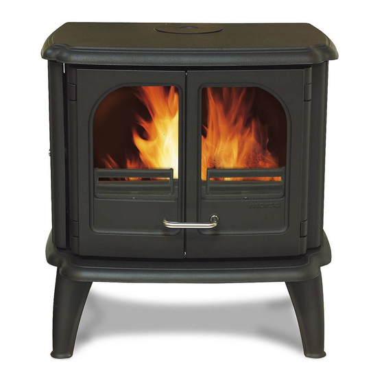
Morso 3600 series Installation And Operating Instructions Manual
Hide thumbs
Also See for 3600 series:
- Instruction manual (12 pages) ,
- Installation and operating instructions manual (24 pages) ,
- Installation instructions (4 pages)
Table of Contents
Advertisement
Quick Links
Installation and Operating Instructions
3600 series
For use in North America
Read this entire manual before you install and use your new room heater. If this room heater is
not properly installed, a house fire may result. To reduce the risk of fire, follow the installation
instructions. Failure to follow instructions may result in property damage, bodily injury, or
even death.
Contact local building officials about restrictions and installation/inspection-requirements
in your area.
Save these instructions
MORSØ JERNSTØBERI A/S . DK-7900 NYKØBING MORS
E-Mail: stoves@morsoe.com · Website: www.morsoe.com
1
A French version of the manual can be downloaded at www.morsona.com
Advertisement
Table of Contents

Summary of Contents for Morso 3600 series
- Page 1 Installation and Operating Instructions 3600 series For use in North America Read this entire manual before you install and use your new room heater. If this room heater is not properly installed, a house fire may result. To reduce the risk of fire, follow the installation instructions.
-
Page 2: Table Of Contents
We congratulate you on your choice of a Morsø stove. Morsø has been producing some of the world’s best stoves since 1853. If you follow this installation- and operating instruction carefully, we can assure you CONTENTS: many years of warmth and pleasure. Installation of your Morsø... -
Page 3: Installation Of Your Morsø Stove
1.3 The chimney / flue system 1.0 Installation of your Morsø stove Note that the flue system must be independently secured and must not rely on the stove for support. Installation of woodburning stoves must be safe and legal. The stove must not be connected to a chimney flue serving any other appliance. If your Morsø... -
Page 4: Flue Connection
1.4 Flue Connection The stove is supplied from the factory with a flue collar fitted to the top plate and a round blanking plate blocking off the rear flue exit (behind the rear shield plate). Use a 24 MSG black or blue chimney connector or listed double wall chimney connector. Refer to local codes and the chimney manufacturer’s instructions for precautions required for passing a chimney through a combustible wall or ceiling. -
Page 5: Positioning The Stove
1.6 Positioning the stove Distance to walls and lintel When the stove is positioned near combustible materials, observe all current local and national building regulations with regards to clearances. Whatever regulations apply to your area, do not in any case install the stove within 8 inches of combustible materials around the sides or 16 inches above the top of the stove (fireplace installations require greater clearances above the stove - see below in the clearance chart). -
Page 6: Operation
Distance to furniture 2.0 Operation The recommended minimum distance from stove to furniture is 30 inches. Note that some furniture is more easily affected by heat and may need to be moved to a greater distance. This 2.1 Before you start firing is your responsibility. -
Page 7: Lighting And Loading Intervals
Secondary Air is right to the firebox using specially designed baffle at the back of the firebox.The secondary air is injected into the flue gases both above and in front of the fire resulting in a cleaner, Do not for any reason attempt to increase the firing of your heater by altering the air control more efficient combustion process. -
Page 8: Maintenance
1. When you open the door, you will find two small M4 unbraco screws, one in each hinge. Uns- 3.0 MAINTENANCE crew the two screws, lift the door off the hinges and place it face down on a sheet of cardboard or other nonabrasive fabric. -
Page 9: Cleaning The Stove And The Flue
3.3 Cleaning the Stove and the Flue Clean the chimney connector disconnecting the sections, taking them outside, and removing Check for soot above the baffle plate and around the flue outlet every month or so to start with. any deposits with a stiff wire brush. Reinstall the connetor sections after cleaning, being sure to If the stove suddenly becomes sluggish, check for a soot fall around the flue collar or in the flue/ secure the joints between individual sections with sheet metal screws. -
Page 10: Parts Diagram
3.6 Parts list for model Morsø 3600 3.5 Parts diagram for model Morsø 3600 Pos.No. Parts 3610 3640 Base plate 443601XX 443601XX Front frame 443602XX 443602XX Door right 443603XX 443603XX Side plate 443604XX 443631XX Side frame 443605XX 443605XX Door side 443606XX 443630XX Inside rear plate... - Page 11 Pos.No. Parts 3610 3640 Distance tube 545007 545007 Pressure spring, stainless 79048600 79048600 Glass fitting 54146361 54146361 Washer 791891 791891 Washer 746006 746006 74701000 74701000 Washer 736108 736108 Screw 731670 731670 Washer 791824 791824 Screw 73961700 73961700 Screw 731612 731612 Screw 731616 731616...


Need help?
Do you have a question about the 3600 series and is the answer not in the manual?
Questions and answers