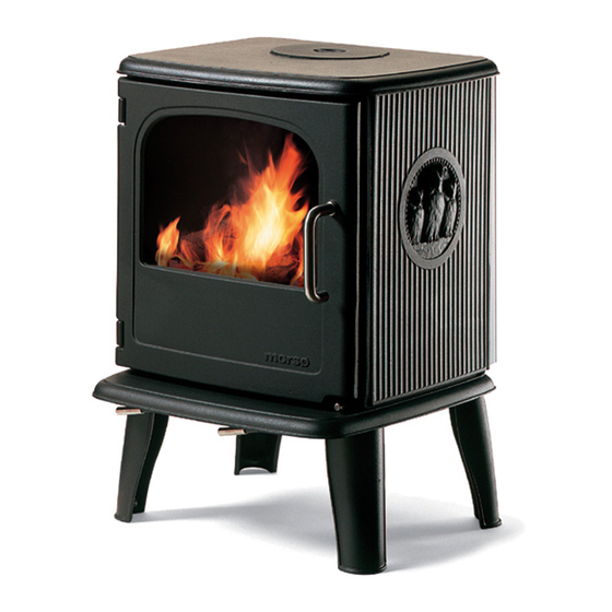
Morso 3410 Installation And Operating Instructions Manual
Morso 3410; 3440; 3450 burning stoves
Hide thumbs
Also See for 3410:
- Instructions for installation and use manual (20 pages) ,
- Installation and operation instructions manual (24 pages) ,
- Assembly and user instructions manual (12 pages)
Table of Contents
Advertisement
Installation and Operating Instructions
3410, 3440 and 3450
Read this entire manual before you install and use your new room heater. If this room
heater is not properly installed, a house fire may result. To reduce the risk of fire, follow
the installation instructions. Failure to follow instructions may result in property damage,
bodily injury, or even death.
Contact local building officials about restrictions and installation/inspection-requirements
in your area.
MORSØ JERNSTØBERI A/S . DK-7900 NYKØBING MORS
E-Mail: stoves@morsoe.com · Website: www.morsoe.com
1011 Highway 52 West - Portland TN - 37148 - USA
For use in North America
Save these instructions
Distributed by: MORSO US LLC
1
Advertisement
Table of Contents

Related Manuals for Morso 3410


Summary of Contents for Morso 3410
- Page 1 Installation and Operating Instructions 3410, 3440 and 3450 For use in North America Read this entire manual before you install and use your new room heater. If this room heater is not properly installed, a house fire may result. To reduce the risk of fire, follow the installation instructions.
- Page 2 The Morsø 3410 owl, 3440 and 3450 meet the U.S. Environmental Protection Agency’s emission limits for wood heaters sold on or after July 1, 1990 The Morsø 3410 owl, 3440 and 3450 are listed by OMNI-Test Laboratories, Inc. The test standards are ANSI/UL-1482 for the United States and ULC S627 for Canada.
-
Page 3: Table Of Contents
CONTENTS: Installation of your Morsø stove Checking loose parts in the stove The chimney / flue system Flue Connection Connection to existing chimney Positioning the stove Mobile Home Installation Operation Before you start firing Lighting and loading intervals Maintenance Exterior maintenance Internal maintenance Cleaning the Stove and the Flue Leaving the stove for extended periods... -
Page 4: Installation Of Your Morsø Stove
1.0 Installation of your Morsø stove Installation of woodburning stoves must be safe and legal. If your Morsø stove is not installed correctly, it may cause a house fire. To reduce the risk of fire, the installation instructions must be followed carefully. Contact the local building officials about restrictions and installation inspection in your area. -
Page 5: The Chimney / Flue System
1.2 The chimney / flue system Note that the flue system must be independently secured and must not rely on the stove for support. The stove must not be connected to a chimney flue serving any other appliance. (Several flues may run up a single chimney stack; use one flueway per appliance). Use a residential type masonry or listed type HT factory-built chimney. -
Page 6: Flue Connection
1.3 Flue Connection The stove is supplied from the factory with a flue collar fitted to the top plate and a round blanking plate blocking off the rear flue exit (behind the rear shield plate). Use a 24 MSG black or blue chimney connector or listed double wall chimney connector. Refer to local codes and the chimney manufacturer’s instructions for precautions required for passing a chimney through a combustible wall or ceiling. -
Page 8: Positioning The Stove
When the stove is positioned near non-combustible materials, a gap of 4 inches or more is recommended for cleaning purposes and to ensure that heat circulates around the stove and out into the room. 3410 and 3450 CLEARANCE REQUIREMENTS STANDARD RESIDENTIAL INSTALLATION... - Page 9 3410, 3440 and 3450 CLEARANCE REQUIREMENTS STANDARD RESIDENTIAL INSTALLATION FIREPLACE HEARTH INSTALLATION (ALCOVE) CANADA SIDEWALL TO UNIT 20’’ 510 mm. COMBUSTIBLE MANTEL TO UNIT 19’’ 480 mm. TOP FACING 11’’ 280 mm. SIDE FACING HEARTH EXTENDING, FRONT HEARTH EXTENDING, SIDE...
-
Page 10: Mobile Home Installation
1.6 Mobile Home Installation The Morsø 3410, 3440 and 3450 can be installed in a mobile home if equipped with an outside combustion air kit, a terminal cap with a spark arrestor, and if it meets the following installation requirements: •... - Page 11 • Follow the chimney and chimney connector manufacturer’s instructions when in- stalling the flue system for use in a mobile home. • Outside air kit should be installed according to installation guide in the kit. • Intake air piping can be installed through the floor into a vented crawl space or through the wall of the residence to obtain outside air.
-
Page 12: Operation
2.0 Operation 2.1 Before you start firing For Use with Solid Wood Fuel Only. Do Not Overfire, If Heater or Chimney Connector Glows You Are Overfiring. Inspect and Clean Chimney Frequently. Under Certain Conditions of use creosote buildup may occur rapidly. Because of risk of smoke and flame spillage, operate only with door fully closed. -
Page 13: Lighting And Loading Intervals
the firebox. The secondary air is injected into the flue gases both above and in front of the fire resulting in a cleaner, more efficient combustion process. The supply of secondary air is fixed open and is not adjustable. For extra safety, your stove has been fitted with a removable handle. When not in use the handle can be stored using the lug behind the right leg of the stove. - Page 14 Do not for any reason attempt to increase the firing of your heater by altering the air control adjustment range outlined in these directions. Warning: Fireplace stoves must never be left unattended with doors open. If the door is left partly open, gas and flame may be drawn out of the fireplace stove opening, creating risks from both fire and smoke.
-
Page 15: Maintenance
3.0 MAINTENANCE When perfoming maintenance on your stove, always protect yourself, using safety goggles and gloves 3.1 Exterior Maintenance The stove surface is painted with heat-resistant Senotherm paint. It is best kept clean by vacuuming with a soft brush attachment or by wiping with a lint-free cloth. Over a period of time, the painted surface may become slightly grey. - Page 16 2. Unscrew the eight bolts that secure the glass. (In the event that a bolt sheers off when being unscrewed, remove the remaining body of the bolt by drilling down its cnetre with 1/8 inch high speed steel drill bit. Smaller drill bits may be successful, but do not use a lager bit.
-
Page 17: Cleaning The Stove And The Flue
Ceramic Gasket The gasket around the perimeter of the door may harden over a period of time. It should be replaced if it becomes difficult to close the door or if air starts to leak in around the perimeter of the door, causing the fire to become a little less controllable. -
Page 18: Leaving The Stove For Extended Periods
any deposits with a stiff wire brush. Reinstall the connetor sections after cleaning, being sure to secure the joints between individual sections with sheet metal screws. If you cannot inspect or clean the chimney yourself, contact your local Morsø Deler or a professional chimney sweep. -
Page 19: Parts Diagram
3.5 Parts diagram for the model Morsø 3410 and 3440... -
Page 20: Parts List
3.6 Parts list for the model Morsø 3410, 3440 and 3450 Pos.No. Parts 3410 3440 3450 Intermediate frame 44341800 44341800 44341800 Inside top plate 34340800 34340800 34340800 Plate for intermediate frame 71348000 71348000 71348000 Draft reducer 44342400 44342400 44342400 Inside rear plate... - Page 21 Pos.No. Parts 3410 3440 3450 Screw 74160804 74160804 74160804 Screw 74253000 74253000 74253000 Cotter pin 74202000 74202000 74202000 Screw 74251800 74251800 74251800 Screw 73850800 73850800 73850800 Screw 743625 743625 743625 Brass washer 746006 746006 746006 74620500 74620500 74620500 Stainless handle for adjustment...
- Page 24 Morsø Jernstøberi A/S - 26.08.2009 - 72345400 24 24...
Need help?
Do you have a question about the 3410 and is the answer not in the manual?
Questions and answers