Kramer MV-6 User Manual
3g hd-sdi multiviewer
Hide thumbs
Also See for MV-6:
- User manual (42 pages) ,
- Quick start manual (4 pages) ,
- User manual (75 pages)

Related Manuals for Kramer MV-6


Summary of Contents for Kramer MV-6
-
Page 1: User Manual
K R A ME R E LE CT R O N IC S L TD . USER MANUAL MODEL: MV-6 3G HD-SDI Multiviewer P/N: 2900-000737 Rev 8... -
Page 3: Table Of Contents
Freezing/Releasing a Video Output Locking the Front Panel Resetting the Device to Factory Defaults Using the Menu Operating the MV-6 Remotely Operating the MV-6 via the RS-232 Serial Port MV-6 Controller Software The Menu Bar Upgrading the Firmware Technical Specifications... - Page 4 View Modes 12.8 Font Size Figures Figure 1: MV-6 3G HD-SDI Multiviewer Front Panel Figure 2: MV-6 3G HD-SDI Multiviewer Rear Panel Figure 3: Connecting the MV-6 3G HD-SDI Multiviewer Figure 4: Local Area Connection Properties Window Figure 5: Internet Protocol Version 4 Properties Window...
-
Page 5: Introduction
Room Connectivity; GROUP 10: Accessories and Rack Adapters; GROUP 11: Sierra Video Products; GROUP 12: Digital Signage; GROUP 13: Audio; and GROUP 14: Collaboration. Congratulations on purchasing your Kramer MV-6 3G HD-SDI Multiviewer, which is ideal for the following typical applications: ... -
Page 6: Getting Started
Avoid interference from neighboring electrical appliances that may adversely influence signal quality Position your Kramer MV-6 away from moisture, excessive sunlight and dust This equipment is to be used only inside a building. It may only be connected to other equipment that is installed inside a building. -
Page 7: Safety Instructions
Kramer Electronics has made arrangements with the European Advanced Recycling Network (EARN) and will cover any costs of treatment, recycling and recovery of waste Kramer Electronics branded equipment on arrival at the EARN facility. For details of Kramer’s recycling arrangements in your particular country go to our recycling pages at http://www.kramerelectronics.com/support/recycling/. -
Page 8: Overview
Overview The MV-6 is a versatile, high-performance video viewer for signals up to 3G HD-SDI. The device can window up to six sources in any layout and output the image in SDI, HDMI and CV formats. Both preprogrammed and customizable screen division is supported. -
Page 9: Accessory To Medical Equipment (Iec 60601-1)
The MV-6 is housed in a 2U height enclosure and is fed from a 100-240 VAC universal switching power supply. The device can be controlled via the front panel buttons and remotely via: RS-232 serial commands transmitted by a PC, touch-screen system or other serial controller ... -
Page 10: Figure 1: Mv-6 3G Hd-Sdi Multiviewer Front Panel
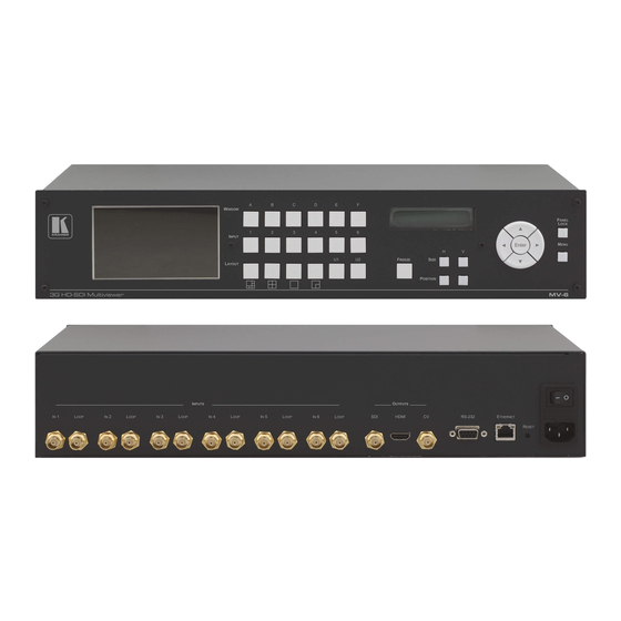
Figure 1: MV-6 3G HD-SDI Multiviewer Front Panel Feature Function LCD Video Preview Screen LCD screen to display the output signal WINDOW Buttons (A to F) Press to select one of the windows INPUT Buttons (1 to 6) Press to select the active input following selection of an active window (using the WINDOW buttons) LCD Menu 2 Line x 16 During normal operation the Window/Input list is displayed. - Page 11 6.3) SIZE Buttons Press either the width (H) or height (V) button to change the size of the active window (see Section 6.9) MENU Button Press to move back one level through the menu (see Section 6.9) MV-6 - Overview...
-
Page 12: Figure 2: Mv-6 3G Hd-Sdi Multiviewer Rear Panel
Figure 2: MV-6 3G HD-SDI Multiviewer Rear Panel Feature Function INPUTS (1 to 6) and Associated BNC Connect Inputs to video sources and Loop outputs to loop video acceptors (see LOOP Outputs (1 to 6) Section 5) RS-232 9-pin D-sub (F) Connector... -
Page 13: Installing In A Rack
Installing in a Rack This section provides instructions for rack mounting the unit. MV-6 - Installing in a Rack... -
Page 14: Connecting The
MV-6. After connecting your MV-6, connect its power and then switch on the power to each device. The MV-6 accepts up to six SD/HD/3G HD-SDI inputs. The device outputs a signal (which can be any combination of the inputs) to the SDI, HDMI and... -
Page 15: Connecting To The Rs-232 Port
Figure 3: Connecting the MV-6 3G HD-SDI Multiviewer Connecting to the RS-232 Port You can connect to the MV-6 via an RS-232 connection using, for example, a PC. Note that a null-modem adapter/connection is not required. To connect to the MV-6 via RS-232: ... -
Page 16: Connecting Via Ethernet
5.2.1 Connecting the Ethernet Port Directly to a PC You can connect the Ethernet port of the MV-6 directly to the Ethernet port on your PC using a crossover cable with RJ-45 connectors. This type of connection is recommended for identifying the MV-6 with the factory configured default IP address. -
Page 17: Figure 4: Local Area Connection Properties Window
4. Highlight either Internet Protocol Version 6 (TCP/IPv6) or Internet Protocol Version 4 (TCP/IPv4) depending on the requirements of your IT system. 5. Click Properties. The Internet Protocol Properties window relevant to your IT system appears. Figure 5: Internet Protocol Version 4 Properties Window MV-6 - Connecting the MV-6... -
Page 18: Figure 6: Internet Protocol Version 6 Properties Window
Figure For TCP/IPv4 you can use any IP address in the range 192.168.1.1 to 192.168.1.255 (excluding 192.168.1.39) that is provided by your IT department. Figure 7: Internet Protocol Properties Window MV-6 - Connecting the MV-6... - Page 19 8. Click Close. 5.2.2 Connecting the Ethernet Port via a Network Hub or Switch You can connect the Ethernet port of the MV-6 to the Ethernet port on a network hub or using a straight-through cable with RJ-45 connectors. 5.2.3...
-
Page 20: Operating The Mv-6 Locally
Operating the MV-6 Locally The MV-6 sports an LCD video preview screen on which the live video output is shown. Changes made to the device configuration are reflected immediately on the screen allowing you to monitor the output in real-time. -
Page 21: Adjusting The Position Of A Window
4. Press Menu twice to exit the window position setting. Defining and Saving a Custom Window Layout In addition to the four predefined window layouts, the MV-6 can store two custom window layouts. Once you have defined a custom window layout you can save it for future recall. -
Page 22: Recalling A Window Layout
Locked message to display and the Lock button to flash To unlock the front panel: Press and hold the Panel Lock button (see PANEL LOCK Button). The button no longer lights and the front panel buttons are unlocked MV-6 - Operating the MV-6 Locally... -
Page 23: Resetting The Device To Factory Defaults
The main menu comprises six sections: Windows (see Section 6.9.1) Output (see Section 6.9.2) Status (see Section 6.9.3) Comm Settings (see Section 6.9.4) User Presets (see Section 6.9.5) System (see Section 6.9.6) MV-6 - Operating the MV-6 Locally... - Page 24 R, G and B Default—R=1, G=101, B=53 values WIN BORDER Turns the window border ON, OFF on or off Default—ON WIN TEXT Turns the window text ON, OFF labels on and off Default—ON MV-6 - Operating the MV-6 Locally...
- Page 25 Saves the current screen layout as a USER PRESET 1, USER user defined layout PRESET 2 Default—USER PRESET 1 LOAD Loads the selected user defined USER PRESET 1, USER screen layout PRESET 2 Default—USER PRESET 1 MV-6 - Operating the MV-6 Locally...
- Page 26 The parameters in the System Sub-Menu display the device versions and set the video screen characteristics. Parameter Description Options FIRMWARE The device firmware version FPGA VER The device FPGA version The device serial number Back Light AUTO, ON Default—AUTO Brightness 0 to 100 Default—100 MV-6 - Operating the MV-6 Locally...
-
Page 27: Operating The Mv-6 Remotely
Section 7.2) Operating the MV-6 via the RS-232 Serial Port Kramer offers free control software that allows you to operate the MV-6 remotely via a PC or serial controller using serial commands (see Section 11). This software can be downloaded from http://www.kramerelectronics.com/support/product_downloads.asp. -
Page 28: Figure 8: Mv-6 Controller Software Main Window
Figure 8: MV-6 Controller Software Main Window Feature Function Menu Bar Operate and configure the device using the Menu Bar options (see Section 7.3) Quick Access Toolbar Operate and configure the device using the quick access toolbar buttons (see Section 7.3.1) -
Page 29: The Menu Bar
Turns the window border on and off Refresh Retrieves full information from the device ABOUT Displays the Step-in Software and Kramer company details Note: Any actions that you are not authorized to perform are grayed out. MV-6 - Operating the MV-6 Remotely... -
Page 30: Figure 9: Quick Access Toolbar
Set the screen to display the 4-window configuration Set the screen to display the single-window configuration Set the screen to display the 2-window configuration Freezes the output video Sets the visibility of the active window MV-6 - Operating the MV-6 Remotely... -
Page 31: Figure 10: Connect Window
For a serial connection, select the required Com port from the drop- down list. 3. Click Connect. If the connection is successful, the main window shown in Figure 8 appears. If the connection is not successful, a Timeout error message appears. MV-6 - Operating the MV-6 Remotely... -
Page 32: Figure 11: Windows Position
Figure 11: Windows Position To change the size of a window: Click, hold and drag the required window handle To change the position of a window: Click, hold and drag anywhere in the window MV-6 - Operating the MV-6 Remotely... -
Page 33: Figure 12: Switch Buttons
Inputs Buttons (1 to 6) Press to select an input to assign to a window (see Section 7.3.8) Camera Input button label (see Section 7.3.8) Input icon User assigned icon for this input (see Section 7.3.8) MV-6 - Operating the MV-6 Remotely... -
Page 34: Figure 13: Layer Order
1. Click and hold on the layer that you want to move. 2. Drag the layer to the right or left into the required position and release. The layer is placed in the required position. MV-6 - Operating the MV-6 Remotely... -
Page 35: Figure 14: Switching An Input To A Window
The window is selected and the button changes to a solid color as shown Figure Figure 14: Switching an Input to a Window 2. Click on the required Inputs button. The input is assigned to the previously selected window and the button changes to a solid color. MV-6 - Operating the MV-6 Remotely... -
Page 36: Figure 15: Windows Setup Window
5. In the Position fields, enter the x and y position for the window. 6. In the Size fields, enter the width and height for the window. 7. Click OK. The Window setup is changed. MV-6 - Operating the MV-6 Remotely... -
Page 37: Figure 16: Input Button Properties Window
3. Select the required icon from the list or click on the Select icon from file button and browse to the required file. 4. Modify the Text Overlay properties as required. 5. Click OK. The input button characteristics are changed. MV-6 - Operating the MV-6 Remotely... -
Page 38: Figure 17: Device Details Window
2. Modify the parameters as required. For each modified parameter, click Set Value. 3. Click Close. Note: If you modify any of the IP parameters you need to reconnect to the device with the new parameters. MV-6 - Operating the MV-6 Remotely... - Page 39 To set the IP network parameters: 1. Click Unit > Device Details. 2. Under Connectivity, edit the required parameter. 3. Click Set Value. A confirmation message appears. 4. Click OK. The parameter is set. 5. Reboot the device. MV-6 - Operating the MV-6 Remotely...
-
Page 40: Upgrading The Firmware
Figure 18: About MV-6 Window 2. Click OK to close the window. Upgrading the Firmware For instructions on upgrading the firmware see “Upgrading the MV-6 Firmware Using the K-Upload Software”. Note: To upgrade to firmware V3.2.7321 you must use K-Upload software V1.0.0.50. -
Page 41: Technical Specifications
HUMIDITY: 10% to 90%, RHL non-condensing DIMENSIONS: 19" x 7.4" x 2U (W, D, H) rack mountable WEIGHT: 3.1kg (6.83lbs) approx. Power cord, Rack “ears” INCLUDED ACCESSORIES: Specifications are subject to change without notice at http://www.kramerelectronics.com MV-6 - Technical Specifications... -
Page 42: Default Communication Parameters
Factory Reset button, located on the rear panel of the unit IP Address: 192.168.1.39 Subnet mask: 255.255.255.0 Default gateway: 192.168.1.1 TCP Port #: 5000 5000 UDP Port #: 50000 50000 Maximum UDP Ports: Maximum TCP Ports: MV-6 - Default Communication Parameters... -
Page 43: Kramer Protocol 3000 Syntax
Kramer Protocol 3000 Syntax The MV-6 can be operated using serial commands from a PC, remote controller or touch screen using the Kramer Protocol 3000. With Kramer Protocol 3000 you can control a device from any standard terminal software (for example, the Windows® HyperTerminal Application). -
Page 44: Command Terms
Device address (Optional when directly connected to the device) K-Net Device ID or MACHINE NUMBER followed by '@' (ex. #02@CR LF ) Query sign '?' follows some commands to define a query request. All outputs sign '*' defines all outputs. MV-6 - Kramer Protocol 3000 Syntax... -
Page 45: Entering Commands
You can directly enter all commands using a terminal with ASCII communication software, such as HyperTerminal, Hercules, etc. Connect the terminal to the serial, Ethernet, or USB port on the Kramer device. To enter CR, press the Enter key. (LF is also sent but is ignored by the command parser). -
Page 46: Maximum String Length
10.7 Maximum String Length 64 characters 10.8 Backward Support Protocol 2000 is transparently supported by Protocol 3000. You can switch between protocols using a switch protocol command from either platform. MV-6 - Kramer Protocol 3000 Syntax... -
Page 47: Protocol 3000 Commands
Command Type - System-mandatory Command Name Permission Transparency Set: End User Public Get: Description Syntax Set: Protocol handshaking #␍ Get: Response ~nn@␠OK␍␊ Parameters Response Triggers Notes Use to validate the Protocol 3000 connection and get the machine number MV-6 - Protocol 3000 Commands... - Page 48 End User Public Get: Description Syntax Reset device to factory default Set: #FACTORY␍ configuration Get: Response ~nn@FACTORY␠OK␍␊ Parameters Response Triggers Notes This command deletes all user data from the device. The deletion can take some time. MV-6 - Protocol 3000 Commands...
- Page 49 Command Type - System-mandatory Command Name Permission Transparency Set: Get: MODEL? End User Public Description Syntax Set: Get: Get device model #MODEL?␍ Response ~nn@MODEL␠model_name␍␊ Parameters model_name - String of up to 19 printable ASCII chars Response Triggers Notes MV-6 - Protocol 3000 Commands...
- Page 50 Notes To avoid locking the port due to a USB bug in Windows, disconnect USB connections immediately after running this command. If the port was locked, disconnect and reconnect the cable to reopen the port. MV-6 - Protocol 3000 Commands...
- Page 51 Command Name Permission Transparency Set: Get: VERSION? End User Public Description Syntax Set: Get: Get firmware version number #VERSION?␍ Response ~nn@VERSION␠firmware_version␍␊ Parameters firmware_version - XX.XX.XXXX where the digit groups are: major.minor.build version Response Triggers Notes MV-6 - Protocol 3000 Commands...
-
Page 52: System Commands
Public Description Syntax Set: Get: Get current FPGA version #FPGA-VER?␠id␍ Response ~nn@FPGA-VER␠id, expected_ver, actual_ver␍␊ Parameters id - FPGA id expected_ver - expected FPGA version for current firmware actual_ver - actual FPGA version Response Triggers Notes MV-6 - Protocol 3000 Commands... - Page 53 ~nn@MACH-NUM␠machine_numberOK␍␊ Parameters machine_number - new device machine number Response Triggers Notes Some devices do not set the new machine number until the device is restarted Some devices can change the machine number only from DIP-switches MV-6 - Protocol 3000 Commands...
- Page 54 Get: Description Syntax Reset machine (DNS) name to Set: #NAME-RST␍ factory default Get: Response ~nn@NAME-RST␠OK␍␊ Parameters Response Triggers Notes Factory default of machine (DNS) name is “KRAMER_” + 4 last digits of device serial number MV-6 - Protocol 3000 Commands...
- Page 55 Set: Perform firmware upgrade #UPGRADE␍ Get: Response ~nn@UPGRADE␠OK␍␊ Parameters Response Triggers Notes Not necessary for some devices Firmware usually uploads to a device via a command like LDFW Reset the device to complete the process MV-6 - Protocol 3000 Commands...
-
Page 56: Video Commands
After execution, response is sent to the com port from which the Set/Get was received After execution, response is sent to all com ports if BCKGRND was set by any other external control device (button press, device menu and similar) Notes MV-6 - Protocol 3000 Commands... - Page 57 Response is sent to the com port from which the Set (before execution) / Get command was received After execution, response is sent to all com ports if GNLCK was set for any other external control device (button press, device menu and similar) or genlock status changed Notes MV-6 - Protocol 3000 Commands...
- Page 58 Device sends as answer actual VIC ID of native resolution “Get” command with is_native=ON returns native resolution VIC, with is_native=OFF returns current resolution To use “custom resolutions” (entries 100-105 in Section 12.6 Custom Resolution Parameters), define them using the DEF-RES command MV-6 - Protocol 3000 Commands...
-
Page 59: Multiviewer Commands
Parameters Set: win_num - 1-4; x0,y0 - top-left coordinate, x1, y1 - bottom-right coordinate Get: x0,x1 <=180 y0,y1 <=144(for PAL) y0,y1 <= 120(for NTSC) win_num = 1-4 or 0 (for output window) Response Triggers Notes MV-6 - Protocol 3000 Commands... - Page 60 After execution, response is sent to the com port from which the Set/Get was received After execution, response is sent to all com ports if OVRL was set by any other external control device (button press, device menu and similar) Notes MV-6 - Protocol 3000 Commands...
- Page 61 After execution, response is sent to the com port from which the Set/Get was received After execution, response is sent to all com ports if OVRLBK was set by any other external control device (button press, device menu and similar) Notes MV-6 - Protocol 3000 Commands...
- Page 62 After execution, response is sent to the com port from which the Set/Get was received After execution, response is sent to all com ports if W-ACTIVE was set by any other external control device (button press, device menu and similar) Notes MV-6 - Protocol 3000 Commands...
- Page 63 After execution, response is sent to the com port from which the Set/Get was received After execution, response is sent to all com ports if W-FRZ was set by any other external control device (button press, device menu and similar) Notes MV-6 - Protocol 3000 Commands...
- Page 64 After execution, response is sent to the com port from which the Set/Get was received After execution, response is sent to all com ports if W-SRC was set by any other external control device (button press, device menu and similar) Notes src limits can vary for different devices MV-6 - Protocol 3000 Commands...
-
Page 65: Communication Commands
#ETH-PORT?␠portType, portNum␍ Response ~nn@ ETH-PORT␠portType, ETHPort, portNum␍␊ Parameters portNum - 1-4 TCP/UDP port enumerator (equals the connected com port number from the tunneling port) portType - TCP/UDP ETHPort - TCP/UDP port number Response Triggers Notes MV-6 - Protocol 3000 Commands... - Page 66 Get: ~nn@NET-GATE␠ip_address␍␊ Parameters ip_address - format: xxx.xxx.xxx.xxx Response Triggers Notes A network gateway connects the device via another network and maybe over the Internet. Be careful of security problems. For proper settings consult your network administrator MV-6 - Protocol 3000 Commands...
- Page 67 Command Name Permission Transparency Set: Get: NET-MAC? End User Public Description Syntax Set: Get: Get MAC address #NET-MAC?␍ Response ~nn@NET-MAC␠mac_address␍␊ Parameters mac_address - Unique MAC address. Format: XX-XX-XX-XX-XX-XX where X is hex digit Response Triggers Notes MV-6 - Protocol 3000 Commands...
- Page 68 Get subnet mask #NET-MASK?␍ Response Set: ~nn@NET-MASK␠net_mask␠OK␍␊ Get: ~nn@NET-MASK␠net_mask␍␊ Parameters net_mask - format: xxx.xxx.xxx.xxx Response Triggers The subnet mask limits the Ethernet connection within the local network For proper settings consult your network administrator Notes MV-6 - Protocol 3000 Commands...
-
Page 69: Parameters
(Reserved) 12.5 Video Resolutions VIC Number Resolution No Signal (for input) / Native - EDID (for output) 640x480p @59.94Hz/60Hz 720x480p @59.94Hz/60Hz 720x480p @59.94Hz/60Hz 1280x720p @59.94Hz/60Hz 1920x1080i @59.94Hz/60Hz 720(1440)x480i @59.94Hz/60Hz 720(1440)x480i @59.94Hz/60Hz 720(1440)x240p @59.94Hz/60Hz 720(1440)x240p @59.94Hz/60Hz 2880x480i @59.94Hz/60Hz MV-6 - Parameters... - Page 70 1920x1080p @29.97Hz/30Hz 2880x480p @59.94Hz/60Hz 2880x480p @59.94Hz/60Hz 2880x576p @50Hz 2880x576p @50Hz 1920x1080i @50Hz 1920x1080i @100Hz 1280x720p @100Hz 720x576p @100Hz 720x576p @100Hz 720(1440)x576i @100Hz 720(1440)x576i @100Hz 1920x1080i @119.88/120Hz 1280x720p @119.88/120Hz 720x480p @119.88/120Hz 720x480p @119.88/120Hz 720(1440)x480i @119.88/120Hz 720(1440)x480i @119.88/120Hz 720x576p @200Hz MV-6 - Parameters...
-
Page 71: Custom Resolution Parameters
104-254 (Reserved) 12.6 Custom Resolution Parameters Number Value Width Height HTotal VTotal HSync width HSync back porch VSync width VSync back porch Frame rate Interlaced (0)/Progressive (1) 12.7 View Modes Number Value PIP off PIP on Preview MV-6 - Parameters... -
Page 72: Font Size
12.8 Font Size Number Value Small Medium Large MV-6 - Parameters... - Page 74 For the latest information on our products and a list of Kramer distributors, visit our Web site where updates to this user manual may be found. We welcome your questions, comments, and feedback. Web site: www.kramerelectronics.com E-mail: info@kramerel.com SAFETY WARNING...
Need help?
Do you have a question about the MV-6 and is the answer not in the manual?
Questions and answers