
Related Manuals for Kramer MV-6-MD


Summary of Contents for Kramer MV-6-MD
- Page 1 K R A ME R E LE CT R O N IC S L TD . USER MANUAL MODEL: MV-6 3G HD-SDI Multiviewer P/N: 2900-000737 Rev 11...
-
Page 3: Table Of Contents
Operating the MV-6 Remotely Operating the MV-6 via the RS-232 Serial Port MV-6 Controller Software The Menu Bar Upgrading the Firmware Technical Specifications Default Communication Parameters Kramer Protocol 3000 Syntax 10.1 Host Message Format 10.2 Device Message Format 10.3 Command Terms 10.4... - Page 4 12.5 Video Resolutions 12.6 Custom Resolution Parameters 12.7 View Modes 12.8 Font Size Figures Figure 1: MV-6 3G HD-SDI Multiviewer Front Panel Figure 2: MV-6 3G HD-SDI Multiviewer Rear Panel Figure 3: Connecting the MV-6 3G HD-SDI Multiviewer Figure 4: Local Area Connection Properties Window Figure 5: Internet Protocol Version 4 Properties Window Figure 6: Internet Protocol Version 6 Properties Window Figure 7: Internet Protocol Properties Window...
-
Page 5: Introduction
Introduction Welcome to Kramer Electronics! Since 1981, Kramer Electronics has been providing a world of unique, creative, and affordable solutions to the vast range of problems that confront video, audio, presentation, and broadcasting professionals on a daily basis. In recent years, we have redesigned and upgraded most of our... -
Page 6: Getting Started
Avoid interference from neighboring electrical appliances that may adversely influence signal quality Position your Kramer MV-6 away from moisture, excessive sunlight and dust This equipment is to be used only inside a building. It may only be connected to other equipment that is installed inside a building. -
Page 7: Safety Instructions
Kramer Electronics has made arrangements with the European Advanced Recycling Network (EARN) and will cover any costs of treatment, recycling and recovery of waste Kramer Electronics branded equipment on arrival at the EARN facility. For details of Kramer’s recycling arrangements in your particular country go to our recycling pages at http://www.kramerelectronics.com/support/recycling/. -
Page 8: Overview
Front panel color LCD preview screen for real-time display of output Kramer re-Klocking™ and equalization on each input – rebuilds the digital signal to travel longer distances Flexible control options; front panel with menu LCD and on-screen displays, Ethernet, and RS-232 ... -
Page 9: Accessory To Medical Equipment (Iec 60601-1)
The MV-6 is housed in a 2U height enclosure and is fed from a 100-240 VAC universal switching power supply. The device can be controlled via the front panel buttons and remotely via: RS-232 serial commands transmitted by a PC, touch-screen system or other serial controller ... -
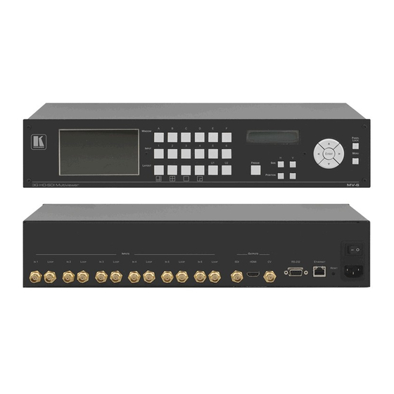
Page 10: Figure 1: Mv-6 3G Hd-Sdi Multiviewer Front Panel
Figure 1: MV-6 3G HD-SDI Multiviewer Front Panel Feature Function LCD Video Preview Screen LCD screen to display the output signal WINDOW Buttons (A to F) Press to select one of the windows INPUT Buttons (1 to 6) Press to select the active input following selection of an active window (using the WINDOW buttons) LCD Menu 2 Line x 16 During normal operation the Window/Input list is displayed. - Page 11 U1 Button Press to select the first user-definable output window pattern (programmed using the menu, see Section 7 U2 Button Press to select the second user-definable output window pattern (programmed using the menu, see Section 7 Section 6 FREEZE Button Press to freeze the selected video window (see POSITION Buttons...
-
Page 12: Figure 2: Mv-6 3G Hd-Sdi Multiviewer Rear Panel
Figure 2: MV-6 3G HD-SDI Multiviewer Rear Panel Feature Function INPUTS (1 to 6) and Associated BNC Connect Inputs to video sources and Loop outputs to loop video acceptors (see Section 5 ) LOOP Outputs (1 to 6) Section 5 RS-232 9-pin D-sub (F) Connector Connect to the serial port on a PC or remote controller (see Mains Power Fuse... -
Page 13: Installing In A Rack
Installing in a Rack This section provides instructions for rack mounting the unit. MV-6 - Installing in a Rack... -
Page 14: Connecting The
Connecting the MV-6 Always switch off the power to each device before connecting it to your MV-6. After connecting your MV-6, connect its power and then switch on the power to each device. The MV-6 accepts up to six SD/HD/3G HD-SDI inputs. The device outputs a signal (which can be any combination of the inputs) to the SDI, HDMI and composite video connectors as shown in Figure... -
Page 15: Connecting To The Rs-232 Port
Figure 3: Connecting the MV-6 3G HD-SDI Multiviewer Connecting to the RS-232 Port You can connect to the MV-6 via an RS-232 connection using, for example, a PC. Note that a null-modem adapter/connection is not required. To connect to the MV-6 via RS-232: ... -
Page 16: Connecting Via Ethernet
Connecting via Ethernet You can connect to the MV-6 via Ethernet using either of the following methods: Section 5 Directly to the PC using a crossover cable (see .2.1) Via a network hub, switch, or router, using a straight-through cable (see Section ... -
Page 17: Figure 4: Local Area Connection Properties Window
Figure 4: Local Area Connection Properties Window 4. Highlight either Internet Protocol Version 6 (TCP/IPv6) or Internet Protocol Version 4 (TCP/IPv4) depending on the requirements of your IT system. 5. Click Properties. The Internet Protocol Properties window relevant to your IT system appears. -
Page 18: Figure 6: Internet Protocol Version 6 Properties Window
Figure 6: Internet Protocol Version 6 Properties Window 6. Select Use the following IP Address for static IP addressing and fill in the details as shown in Figure For TCP/IPv4 you can use any IP address in the range 192.168.1.1 to 192.168.1.255 (excluding 192.168.1.39) that is provided by your IT department. - Page 19 7. Click OK. 8. Click Close. 5.2.2 Connecting the Ethernet Port via a Network Hub or Switch You can connect the Ethernet port of the MV-6 to the Ethernet port on a network hub or using a straight-through cable with RJ-45 connectors. MV-6 - Connecting the MV-6...
-
Page 20: Operating The Mv-6 Locally
Operating the MV-6 Locally The MV-6 sports an LCD video preview screen on which the live video output is shown. Changes made to the device configuration are reflected immediately on the screen allowing you to monitor the output in real-time. The MV-6 is operated locally using the front panel buttons. -
Page 21: Adjusting The Position Of A Window
3. Use the left (◄) and right (►) buttons to adjust the window width, and use the up (▲) and down button (▼) to adjust the window height. The size changes in real-time. 4. Press Menu twice to exit the window size setting. Adjusting the Position of a Window The horizontal and vertical position of each window can be modified. -
Page 22: Recalling A Window Layout
Recalling a Window Layout You can select any of the four predefined or two custom window layouts using the window layout buttons. To select a window layout: Press one of the six screen layout buttons. The button flashes quickly three times and the window layout is recalled from the memory Freezing/Releasing a Video Output To freeze/release a video output:... -
Page 23: Resetting The Device To Factory Defaults
Resetting the Device to Factory Defaults To reset the device to the factory defaults: 1. Turn the device off. 2. Press and hold the Reset button on the rear panel of the device. 3. While holding the button depressed, turn the device on. 4. - Page 24 6.9.1 Windows Sub-Menu The parameters in the Windows Sub-Menu set the window inputs and characteristics. Parameter Description Values Select window Selects the window to adjust A, B, C, D, E, F Default—F Visibility Makes the selected window visible or non- Visible, visible Non-Visible...
- Page 25 6.9.3 Status Sub-Menu The parameters in the Status Sub-Menu display the input states. Parameter Description Values INPUTS > Displays the input states IN 1 unlocked, IN 2 unlocked, IN 3 unlocked, IN 4 unlocked, IN 5 unlocked, IN 6 unlocked GENLOCK unlocked Displays the Genlock state 6.9.4...
- Page 26 6.9.6 System Sub-Menu The parameters in the System Sub-Menu display the device versions and set the video screen characteristics. Parameter Description Options FIRMWARE The device firmware version FPGA VER The device FPGA version The device serial number Back Light AUTO, ON Default—AUTO Brightness 0 to 100 Default—100 MV-6 - Operating the MV-6 Locally...
-
Page 27: Operating The Mv-6 Remotely
Section 7 Ethernet port (see Operating the MV-6 via the RS-232 Serial Port Kramer offers free control software that allows you to operate the MV-6 remotely via a PC or serial controller using serial commands (see Section 1 1). -
Page 28: Figure 8: Mv-6 Controller Software Main Window
Figure 8: MV-6 Controller Software Main Window Feature Function Menu Bar Operate and configure the device using the Menu Bar Section 7 options (see Quick Access Toolbar Operate and configure the device using the quick Section 7 access toolbar buttons (see .3.1) Windows Position Modify window size and position by dragging and... -
Page 29: The Menu Bar
Turns the window border on and off Refresh Retrieves full information from the device ABOUT Displays the Step-in Software and Kramer company details Note: Any actions that you are not authorized to perform are grayed out. MV-6 - Operating the MV-6 Remotely... -
Page 30: Figure 9: Quick Access Toolbar
7.3.1 The Quick Access Toolbar The Quick Access Toolbar buttons are shown in Figure Figure 9: Quick Access Toolbar Feature Description Open an existing project Save the current project Section 7 Connects to and disconnects from the device (see .3.2) Press Take to enable multiple off-line changes to be made. -
Page 31: Figure 10: Connect Window
7.3.2 Connecting to the Device To connect to the device: 1. Click the Connect button. The window shown in Figure 10 appears. Figure 10: Connect Window 2. Select the required method of connection radio button: For Ethernet, enter the IP address and Port number of the device. To set the default IP address and Port number, press the Default button. -
Page 32: Figure 11: Windows Position
7.3.3 Windows Position The windows can be manually manipulated in size and position in the Window Position area. Figure 11: Windows Position To change the size of a window: Click, hold and drag the required window handle To change the position of a window: ... -
Page 33: Figure 12: Switch Buttons
7.3.4 Switch Buttons The switching configuration can be modified by clicking on the Windows and Inputs buttons. Figure 12: Switch Buttons Description C Window Window identifier (A to F) Windows Buttons (A to Press to select a window to assign to an input (see Section ... -
Page 34: Figure 13: Layer Order
7.3.5 Connection Status The connection status can be one of the following states: Online—the device is connected and being updated in real-time by the software Online, in take mode (not updating device)—the device is connected but changes are only implemented when the Update button is pressed ... -
Page 35: Figure 14: Switching An Input To A Window
7.3.7 Implementing Multiple Actions At Once To implement multiple actions at once: 1. Press the Take button to put the device in off-line mode. The button changes to the Update button and the device is in off-line mode. 2. Perform the required actions, such as, switching and layer order changes. -
Page 36: Figure 15: Windows Setup Window
7.3.9 Changing a Window Setup To change a window setup: 1. Right-click on the relevant Windows button. The Window Setup window appears as shown in Figure Figure 15: Windows Setup Window 2. From the Connect to Input drop-down list, select the required input. 3. -
Page 37: Figure 16: Input Button Properties Window
7.3.10 Changing Input Button Properties To change the properties of an input button: 1. Right-click on the relevant input button. The Input Properties window appears as shown in Figure Figure 16: Input Button Properties Window 2. In the Label text box, enter the required button label. (The label is limited to 10 characters.) 3. -
Page 38: Figure 17: Device Details Window
7.3.11 Changing the Device Details From this window you can change the device name and its IP communication parameters. To change the device details: 1. From the Menu bar, click on Device. The Device Details window appears as shown in Figure Figure 17: Device Details Window 2. - Page 39 7.3.12 Updating the Firmware To update the firmware you must be logged in as Admin. To update the firmware: 1. Download the latest firmware file from http://www.kramerelectronics.com/support/product_downloads.asp. 2. Click Unit > Firmware Update. 3. Browse to the firmware file that you downloaded. 4.
-
Page 40: Upgrading The Firmware
7.3.14 Displaying the MV-6 Software Version Number To display the MV-6 Software version number: 1. From the Menu bar, click About. The About MV6 Controller window appears as shown in Figure Figure 18: About MV-6 Window 2. Click OK to close the window. Upgrading the Firmware For instructions on upgrading the firmware see “Upgrading the MV-6 Firmware Using the K-Upload Software”. -
Page 41: Technical Specifications
Technical Specifications 480i – 59.94 INPUTS: 6 SDI serial SMPTE-259M SMPTE-125M video, 75Ω on 576i – 50 ITU-R BNC connectors BT.656-5 720p – SMPTE-292 SMPTE-296M 59.94/60/50 1080i – SMPTE-274M 59.94/60/50 1080p – 29.97/30/25 23.98/24 23.98sF/24sF 1080p – SMPTE-424M SMPTE-296M 59.94/60/50 800mVpp /75Ω... -
Page 42: Default Communication Parameters
Default Communication Parameters RS-232 Protocol 3000 Baud Rate: 115200 Data Bits: Stop Bits: Parity: None Command Format: ASCII Example (Output 1 to Input 2): #V 2>1CR Ethernet To reset the IP settings to the factory reset values, power cycle the device while holding in the Factory Reset button, located on the rear panel of the unit IP Address:... -
Page 43: Kramer Protocol 3000 Syntax
The MV-6 can be operated using serial commands from a PC, remote controller or touch screen using the Kramer Protocol 3000. With Kramer Protocol 3000 you can control a device from any standard terminal software (for example, the Windows® HyperTerminal Application). -
Page 44: Command Terms
Device address (Optional when directly connected to the device) K-Net Device ID or MACHINE NUMBER followed by '@' (ex. #02@CR LF ) Query sign '?' follows some commands to define a query request. All outputs sign '*' defines all outputs. MV-6 - Kramer Protocol 3000 Syntax... -
Page 45: Entering Commands
You can directly enter all commands using a terminal with ASCII communication software, such as HyperTerminal, Hercules, etc. Connect the terminal to the serial, Ethernet, or USB port on the Kramer device. To enter CR, press the Enter key. (LF is also sent but is ignored by the command parser). -
Page 46: Maximum String Length
10.7 Maximum String Length 64 characters. MV-6 - Kramer Protocol 3000 Syntax... -
Page 47: Protocol 3000 Commands
Protocol 3000 Commands 11.1 System Commands - Mandatory All devices running Protocol 3000 use these commands. Command Description Type Permission Protocol handshaking System-mandatory End User BUILD-DATE? Get device build date System-mandatory End User FACTORY Reset to factory default configuration System-mandatory End User HELP Get command list... - Page 48 Command - BUILD-DATE Command Type - System-mandatory Command Name Permission Transparency Set: BUILD-DATE? Get: End User Public Description Syntax Set: Get device build date #BUILD-DATE␍ Get: Response ~nn@BUILD-DATE␠date␠time␍␊ Parameters date - Format: YYYY/MM/DD where YYYY = Year, MM = Month, DD = Day time - Format: hh:mm:ss where hh = hours, mm = minutes, ss = seconds Response Triggers Notes...
- Page 49 Command - HELP Command Type - System-mandatory Command Name Permission Transparency Set: HELP Get: End User Public Description Syntax Set: 2 options: Get command list or help for specific 1. #HELP␍ Get: command 2. #HELP␠command_name␍ Response 1. Multi-line: ~nn@Device available protocol 3000 commands:␍␊command,␠command…␍␊ To get help for command use: HELP (COMMAND_NAME)␍␊...
- Page 50 Command - PROT-VER? Command Type - System-mandatory Command Name Permission Transparency Set: PROT-VER? Get: End User Public Description Syntax Set: Get: Get device protocol version #PROT-VER?␍ Response ~nn@PROT-VER␠3000:version␍␊ Parameters Version - XX.XX where X is a decimal digit Response Triggers Notes Command - RESET...
- Page 51 Command - Command Type - System-mandatory Command Name Permission Transparency Set: Get: End User Public Description Syntax Set: Get: Get device serial number #SN?␍ Response ~nn@SN␠serial_number␍␊ Parameters serial_number - 11 decimal digits, factory assigned Response Triggers Notes For new products with 14 digit serial numbers, use only the last 11 digits Command - VERSION? Command Type - System-mandatory...
-
Page 52: System Commands
11.2 System Commands Command Description Type Permission FPGA-VER? Get current FPGA version System End User LOCK-FP Set/get front panel lock System Administrator MACH-NUM Set machine number System Administrator NAME Set/get machine (DNS) name System Administrator NAME-RST Reset machine name to factory default (DNS) System Administrator PRST-RCL... - Page 53 Command - LOCK-FP Command Type - System Command Name Permission Transparency Set: LOCK-FP End User Public LOCK-FP? Get: End User Public Description Syntax Option 1: #LOCK-FP␠lock_mode␍ Set: Lock front panel Option 2: #LOCK-FP␠device_id,lock_mode␍ Option 1: #LOCK-FP?␍ Get: Get front panel lock state Option 2: #LOCK-FP?␠device_id␍...
- Page 54 Command - NAME Command Type - System (Ethernet) Command Name Permission Transparency Set: NAME Administrator Public NAME? Get: End User Public Description Syntax Set: Set machine (DNS) name #NAME␠machine_name␍ Get: Get machine (DNS) name #NAME?␍ Response Set: ~nn@NAME␠machine_name␠OK␍␊ Get: ~nn@NAME?␠machine_name␍␊ Parameters machine_name - String of up to 14 alpha-numeric chars (can include hyphen, not at the beginning or end) Response Triggers...
- Page 55 Command - PRST-RCL Command Type - System Command Name Permission Transparency Set: PRST-RCL End User Public Get: Description Syntax #PRST-RCL␠ preset ␍ Set: Recall saved preset list Get: Response ~nn@PRST-RCL␠preset␍␊ Parameters preset - preset number Response Triggers Notes In most units, video and audio presets with the same number are stored and recalled together by commands #PRST-STO and #PRST-RCL Command - UPGRADE...
-
Page 56: Video Commands
11.3 Video Commands Command Description Type Permission BCKGRND Set/get screen background color Video End User GNLCK Set/get genlock state Video End User VID-RES Set/get output resolution Video End User Command - BCKGRND Command Type - Video Command Name Permission Transparency BCKGRND Set: End User... - Page 57 Command - GNLCK Command Type - Video Command Name Permission Transparency Set: GNLCK Administrator Public GNLCK? Get: End User Public Description Syntax Set: Set genlock source and mode #GNLCK␠out,in,type␍ Get: Get genlock source, mode and status #GNLCK?␠out␍ Response Set / Get: ~ nn@GNLCK␠out,in,status ␍␊ Parameters out - output number (1 ..
- Page 58 Command - VID-RES Command Type - Video Command Name Permission Transparency Set: VID-RES End User Public VID-RES? End User Public Description Syntax Set: Set output resolution #VID-RES␠stage, stage_id,is_native,resolution␍ #VID-RES?␠stage,stage_id,is_native ␍ Get: Get output resolution Response ␠stage,stage_id,is_native,resolution␍␊ ~ nn@VID-RES Parameters Section 1 2.4 stage - input/output (see Stage) stage_id - number of chosen stage (1...
-
Page 59: Multiviewer Commands
11.4 Multiviewer Commands Command Description Type Permission CRDT Set/get window size and position Multiviewer End User OVRL Set/get text overlay parameters Multiviewer End User OVRLBK Set/get text overlay background parameters Multiviewer End User OVRLTXT Set/get overlay text Multiviewer End User SRC-BLANK Set/get window visibility Multiviewer... - Page 60 Command - OVRL Command Type - Multiviewer Command Name Permission Transparency Set: OVRL End User Public OVRL? End User Public Description Syntax Set: Set text overlay parameters #OVRL␠stage, stage_id,mode,r,g,b,alpha␍ #OVRL?␠stage, stage_id ␍ Get: Get text overlay parameters Response OVRL␠stage, stage_id,mode,r,g,b,alpha␍␊ ~ nn@ Parameters Section ...
- Page 61 Command - OVRLBK Command Type - Multiviewer Command Name Permission Transparency Set: OVRLBK End User Public OVRLBK? End User Public Description Syntax Set: Set text overlay background parameters #OVRLBK␠stage, stage_id,r,g,b,alpha␍ #OVRLBK?␠stage, stage_id ␍ Get: Get text overlay background parameters Response OVRLBK␠stage, stage_id,r,g,b,alpha␍␊...
- Page 62 Command - OVRLTXT Command Type - Multiviewer Command Name Permission Transparency Set: OVRLTXT End User Public OVRLTXT? End User Public Description Syntax Set: Set overlay text #OVRLTXT␠stage,stage_id,type,size,x,y,string␍ #OVRLTXT?␠stage,stage_id ␍ Get: Get overlay text Response OVRLTXT␠stage,stage_id,type,size,x,y,string␍␊ ~ nn@ Parameters Section 1 2.4 stage - input/output (see Stage) stage_id - number of chosen stage (1..
- Page 63 Command - SRC-VID Command Type - Multiviewer Command Name Permission Transparency Set: SRC-VID End User Public SRC-VID? End User Public Description Syntax Set: Set window input #SRC-VID␠win_num,inp_num␍ Get: Get window input #SRC-VID?␠win_num␍ Response ␠ wnd_num, inp_num␍␊ ~ nn@SRC-VID Parameters Wnd_num - window number to set input Inp_num –...
- Page 64 Command - WND-BRD Command Type - Multiviewer Command Name Permission Transparency Set: WND-BRD End User Public WND-BRD? End User Public Description Syntax Set: Enable/ Disable window border #WND-BRD␠win_num, enable␍ Get: Get window border status #WND-BRD?␠win_num␍ Response WND-BRD␠ id, switch,ColSpace,p1,p2,p3␍␊ ~ nn@ Parameters id - window id Section ...
- Page 65 Command - WND-LR Command Type - Multiviewer Command Name Permission Transparency Set: WND-LR End User Public WND-LR? Get: End User Public Description Syntax Set: Set window overlay order #WND-LR␠win_num,value␍ Get: Get window overlay order #WND-LR?␠win_num␍ Response WND-LR ␠win_num, value␍␊ ~ nn@ Parameters win_num - window number setting layer value - overlay order number...
-
Page 66: Communication Commands
11.5 Communication Commands Command Description Type Permission ETH-PORT Set/get Ethernet port protocol Communication Administrator NET-DHCP Set/get DHCP mode Communication Administrator NET-GATE Set/get gateway IP Communication Administrator NET-IP Set/get IP address Communication Administrator NET-MAC? Get MAC address Communication End User NET-MASK Set/get subnet mask Communication Administrator... - Page 67 Command - NET-DHCP Command Type - Communication Command Name Permission Transparency Set: NET-DHCP Administrator Public NET-DHCP? Get: End User Public Description Syntax Set: Set DHCP mode #NET-DHCP␠mode␍ Get: Get DHCP mode #NET-DHCP?␍ Response Set: ~nn@ NET-DHCP␠mode␠OK␍␊ Get: ~nn@ NET-DHCP␠mode ␍␊ Parameters mode - 0 - Do not use DHCP.
- Page 68 Command - NET-IP Command Type - Communication Command Name Permission Transparency Set: NET-IP Administrator Public NET-IP? Get: End User Public Description Syntax Set: Set IP address #NET-IP␠ip_address␍ Get: Get IP address #NET-IP?␍ Response Set: ~nn@ NET-IP␠ip_address␠OK␍␊ Get: ~nn@ NET-IP␠ip_address␍␊ Parameters ip_address - format: xxx.xxx.xxx.xxx Response Triggers Notes...
- Page 69 Command - NET-MASK Command Type - Communication Command Name Permission Transparency Set: NET-MASK Administrator Public NET-MASK? Get: End User Public Description Syntax Set: Set subnet mask #NET-MASK␠net_mask␍ Get: Get subnet mask #NET-MASK?␍ Response Set: ~nn@NET-MASK␠net_mask␠OK␍␊ Get: ~nn@NET-MASK␠net_mask␍␊ Parameters net_mask - format: xxx.xxx.xxx.xxx Response Triggers The subnet mask limits the Ethernet connection within the local network For proper settings consult your network administrator...
-
Page 70: Parameters
Parameters 12.1 On/Off Number Value 12.2 Color Space Number Value YCbCr 4:2:2 YCbCr 4:4:4 12.3 Genlock Types Number Value Free run Digital Analog 12.4 Stage Number Value Input Output (Reserved) (Reserved) 12.5 Video Resolutions VIC Number Resolution No Signal (for input) / Native - EDID (for output) 640x480p @59.94Hz/60Hz 720x480p @59.94Hz/60Hz 720x480p @59.94Hz/60Hz... - Page 71 VIC Number Resolution 2880x480i @59.94Hz/60Hz 2880x240p @59.94Hz/60Hz 2880x240p @59.94Hz/60Hz 1440x480p @59.94Hz/60Hz 1440x480p @59.94Hz/60Hz 1920x1080p @59.94Hz/60Hz 720x576p @50Hz 720x576p @50Hz 1280x720p @50Hz 1920x1080i @50Hz 720(1440)x576i @50Hz 720(1440)x576i @50Hz 720(1440)x288p @50Hz 720(1440)x288p @50Hz 2880x576i @50Hz 2880x576i @50Hz 2880x288p @50Hz 2880x288p @50Hz 1440x576p @50Hz 1440x576p @50Hz 1920x1080p @50Hz 1920x1080p @23.97Hz/24Hz...
-
Page 72: Custom Resolution Parameters
VIC Number Resolution 720x576p @200Hz 720(1440)x576i @200Hz 720(1440)x576i @200Hz 720x480p @239.76/240Hz 720x480p @239.76/240Hz 720(1440)x480i @239.76/240Hz 720(1440)x480i @239.76/240Hz 1280x720p @23.97Hz/24Hz 1280x720p @25Hz 1280x720p @29.97Hz/30Hz 1920x1080p @119.88/120Hz 1920x1080p @100Hz 65-100 (Reserved) Custom resolution 1 Custom resolution 2 Custom resolution 3 Custom resolution 4 Custom resolution 5 104-254 (Reserved) -
Page 73: Font Size
12.8 Font Size Number Value Small Medium Large MV-6 - Parameters... - Page 75 For the latest information on our products and a list of Kramer distributors, visit our Web site where updates to this user manual may be found. We welcome your questions, comments, and feedback. Web site: www.kramerelectronics.com E-mail: info@kramerel.com SAFETY WARNING...
Need help?
Do you have a question about the MV-6-MD and is the answer not in the manual?
Questions and answers