
Related Manuals for Kramer VP-23C


Summary of Contents for Kramer VP-23C
-
Page 1: User Manual
KR AMER ELECTRON ICS LT D. USER MANUAL MODEL: VP-23C Presentation Switcher P/N: 2900-000202 Rev 3... -
Page 3: Table Of Contents
Kramer Protocol 2000 Figures Figure 1: VP-23C Presentation Switcher Figure 2: VP-23C Presentation Switcher – Underside View Figure 3: Connecting the VP-23C Presentation Switcher Figure 4: Crossed Cable RS-232 Connection Figure 5: Straight Cable RS-232 Connection with a Null Modem Adapter... -
Page 4: Introduction
Introduction Welcome to Kramer Electronics! Since 1981, Kramer Electronics has been providing a world of unique, creative, and affordable solutions to the vast range of problems that confront the video, audio, presentation, and broadcasting professional on a daily basis. In recent years, we have redesigned and upgraded... -
Page 5: Getting Started
(often associated with low quality cables) • Avoid interference from neighboring electrical appliances that may adversely influence signal quality • Position your Kramer VP-23C away from moisture, excessive sunlight and dust VP-23C - Getting Started... -
Page 6: Overview
Overview The VP-23C is a high-quality presentation switcher designed for a wide variety of presentation and multimedia applications. The VP-23C includes four switcher groups, that combine the functions of a 2x1 switcher for composite video, a 2x1 switcher for s-Video, a 2x1 switcher for component video/UXGA, and a 4x1 switcher for VGA/UXGA type signals. -
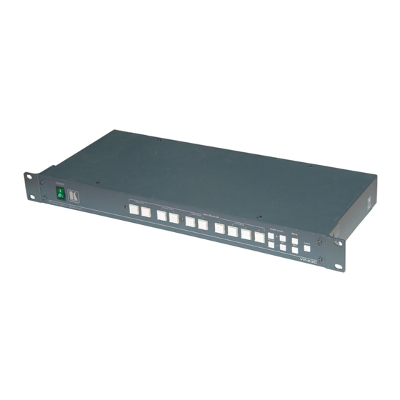
Page 7: Figure 1: Vp-23C Presentation Switcher
Figure 1: VP-23C Presentation Switcher VP-23C - Overview... - Page 8 The input selector button last pressed transmits the audio input signal of the selected channel to the master audio output MIC IN 6.3mm Phone Jack Connector Connects to the microphone Power Connector with Fuse AC connector enabling power supply to the unit VP-23C - Overview...
-
Page 9: Figure 2: Vp-23C Presentation Switcher - Underside View
Figure 2 describes the underside of the VP-23C: Figure 2: VP-23C Presentation Switcher – Underside View Feature Function NORMAL / FLASH Select between NORMAL for normal operation (the factory PROGRAM Switch default), and FLASH PROGRAM to upgrade to the latest Kramer firmware COND. -
Page 10: Installing In A Rack
Pay particular If you are using a Kramer rack attention to situations where electricity is adapter kit (for a machine that is supplied indirectly (when the power cord is not not 19"), see the Rack Adapters... -
Page 11: Connecting The Vp-23C
3, the audio input connections are not shown, except for the microphone. In this example, all the outputs are connected to the same projector. Use the projector controller to switch between the VP-23C video outputs or the projector inputs. To connect the VP-23C, as illustrated in the example in... - Page 12 2) to select a dynamic microphone or a condenser 6. As an option, you can connect a PC and/or controller to the RS-232 port (see Section 5.1). 7. Connect the power cord (not shown in Figure VP-23C - Connecting the VP-23C...
-
Page 13: Connecting To The Vp-23C Via Rs-232
Projector Graphics Source Amplifier Figure 3: Connecting the VP-23C Presentation Switcher Connecting to the VP-23C via RS-232 You can connect to the unit via a crossed RS-232 connection, using for example, a PC. A crossed cable or null-modem is required as shown in method A and B respectively. -
Page 14: Figure 4: Crossed Cable Rs-232 Connection
Method A above) only requires pins 2, 3 and 5 to be connected, you are free to decide whether to connect only these 3 pins or all 9 pins. Null-Modem to PC Adapter Figure 5: Straight Cable RS-232 Connection with a Null Modem Adapter VP-23C - Connecting the VP-23C... -
Page 15: Operating The Vp-23C Presentation Switcher
2 seconds disconnects the output and the button no longer illuminates. The VP-23C operates in the audio-follow-video (AFV) mode so that the audio signal follows the selected input signal in which all operations relate to both the video and the audio channels. - Page 16 When both the MUTE and MIX buttons are on, only the microphone signal is transferred to the master output. The MUTE and MIX buttons can be turned ON or OFF via RS-232 control and their respective buttons on the front panel illuminate. VP-23C - Operating the VP-23C Presentation Switcher...
-
Page 17: Technical Specifications
100-240V AC, 50/60Hz, (115V AC, U.S.A.) 7VA DIMENSIONS: 19” x 7” x 1U (W, D, H) rack-mountable WEIGHT: 2.6kg (8lbs) approx ACCESSORIES: Power cord, null modem adapter, Windows®-based Kramer control software Specifications are subject to change without notice at http://www.kramerelectronics.com VP-23C - Technical Specifications... -
Page 18: Default Communication Parameters
Baud Rate: 9600 Data Bits: Stop Bits: Parity: None Command Format: Example (Output 1 to Input 1): 0x01, 0x81, 0x81, 0x81 Ethernet IP Address: 192.168.1.39 TCP Port Number: 5000 Network Mask: 255.255.255.0 Default Gateway: 192.168.1.1 VP-23C - Default Communication Parameters... -
Page 19: Hex Tables
02 85 81 81 Audio Gain Control Hex Tables The next tables describe the audio gain controls: When controlling the VP-23C via RS-232, read the note to command 42 in the communication protocol. Set Relative Audio Gain of Master Gain by One... -
Page 20: Kramer Protocol 2000
Kramer Protocol 2000 The VS-23C is compatible with Kramer’s Protocol 2000 (version 0.48) (below). This RS-232/RS-485 communication protocol uses four bytes of information as defined below. For RS-232, a null-modem connection between the machine and controller is used. The default data rate is 9600 baud, with no parity, 8 data bits and 1 stop bit. - Page 21 When the PC sends instruction #1 or #2 to the switcher, then, if the instruction is valid, the switcher replies by sending the same four bytes to the PC that were sent (except for the first byte, where the DESTINATION bit is set high). VP-23C - Kramer Protocol 2000...
- Page 22 42 – which is sent prior to the instruction. For example, to request the audio gain value of the master audio output and then send HEX codes To set MIX mode, send hex codes and then send HEX codes VP-23C - Kramer Protocol 2000...
- Page 23 1. Any product which is not distributed by us or which is not purchased from an authorized Kramer dealer. If you are uncertain as to whether a dealer is authorized, please contact Kramer at one of the agents listed in the Web site www.kramerelectronics.com.
- Page 24 For the latest information on our products and a list of Kramer distributors, visit our Web site where updates to this user manual may be found. We welcome your questions, comments, and feedback. Web site: www.kramerelectronics.com E-mail: info@kramerel.com SAFETY WARNING...
Need help?
Do you have a question about the VP-23C and is the answer not in the manual?
Questions and answers