Table of Contents
Advertisement
Advertisement
Table of Contents

Summary of Contents for Magmaweld RA 300 E
- Page 1 USER MANUAL RA 300 E RA 400 E RA 650 E WELDING RECTIFIER www.magmaweld.com...
-
Page 2: Table Of Contents
4.1 MAINTENANCE .............................12 4.2 TROUBLESHOOTING ...........................12 APPENDIX 1: SPARE PARTS LIST FOR RA 300 E / RA 400 E / RA 650 E ...........13 APPENDIX 2: ELECTRICAL DIAGRAM FOR RA 300 E / RA 400 / RA 650 E ..........14... -
Page 3: Safety Rules
HOT PARTS CAN CAUSE SEVERE BURNS Do not touch hot parts Ÿ Allow cooling time before servicing Ÿ If needed to hold hot parts, use appropriate tool, insulating gloves and fireproof clothes. Ÿ RA 300 E / RA 400 E / RA 650 E... - Page 4 MOVING PARTS CAN CAUSE INJURY Keep away from moving parts Ÿ Keep all doors, panels, and guards closed and secured Ÿ Wear shoes with metal protection over the fingers. Ÿ RA 300 E / RA 400 E / RA 650 E...
- Page 5 The components of the gas circuit works under pressure. The service given by unqualified persons may Ÿ cause explosions and operators can be injured seriously RA 300 E / RA 400 E / RA 650 E...
- Page 6 Choose appropriate welding current and welding voltage for the material and its thickness. Ÿ If you will have a long break after welding, turn off the machine after cooler fan cooled the machine. Ÿ RA 300 E / RA 400 E / RA 650 E...
-
Page 7: Technical Information
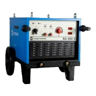
These machines are fan cooled and thermally protected against overheating and phase failures. 1.2 COMPONENTS OF RA 300 E / RA 400 E / RA 650 E RA 650 E Components of the Mach... -
Page 8: Data Plate
Duty cycle defines the percentage of welding time out of a period of 10 minutes at a given current and ambient temperature (standard is 40°C). For example, a welder with 60% duty cycle must be rested (2) for 4 minutes, after 6 minutes of continuous welding (1). RA 300 E / RA 400 E / RA 650 E... -
Page 9: Technical Specifications
OPTIONAL ACCESSORIES Remote Control Box With 10m Cable K301400210 K301400210 K301400310 Remote Control Box With 20m Cable K301400220 K301400220 K301400320 K301400250 K301400250 K301400350 Remote Control Box With 50m Cable RA 300 E / RA 400 E / RA 650 E... -
Page 10: Installation
RA 300 E / RA 400 E / RA 650 E... -
Page 11: Electric Plug Connection
Install the Argon gas regulator onto the Argon gas Ÿ cylinder. onnect the gas hose of the torch Ÿ regulator Figure 5: Connecting Gas Cylinder Figure 4: TIG Welding Connections RA 300 E / RA 400 E / RA 650 E... -
Page 12: Operation
40-60 A 60-90 A 60-90 A 60-100 A 3.25 100-140 A 100-130 A 70-130 A 140-180 A 140-180 A 120-170 A 200-240 A 200-250 A 160-200 A 260-320 A RA 300 E / RA 400 E / RA 650 E... -
Page 13: Maintenance And Troubleshooting
Welding current is low. Diode breakdown Ÿ A primary or secondary coil burn down Ÿ Fan supply voltage phase failure Ÿ Fan is out of order. Fan motor break down Ÿ RA 300 E / RA 400 E / RA 650 E... -
Page 14: Appendix 1: Spare Parts List For Ra 300 E / Ra 400 E / Ra 650 E
APPENDIX 1 SPARE PARTS LIST FOR RA 300 E / RA 400 E / RA 650 E 18 19 MATERIAL CODE DESIGNATION RA 300 E RA 400 E RA 650 E A410500002 A410500002 A410500002 Rheostat 250W A410801003 A410801003 A410801001 Carbon Potentiometer... -
Page 15: Appendix 2: Electrical Diagram For Ra 300 E / Ra 400 / Ra 650 E
APPENDIX 2 ELECTRICAL DIAGRAM FOR RA 300 E / RA 400 E / RA 650E OFF For Rutile and Basic, On For Cellulosic Electrode OFF For Carbon Electrode Current Regulator Arc Force Hot Start RA 300 E / RA 400 E / RA 650 E... - Page 16 FACTORY Organize Sanayi Bölgesi 5.Kısım 5503. Sokak No:1 MANİSA +90 236 226 27 00 +90 236 226 27 28 OWM 02.07.2011 Made in TÜRKİYE www.magmaweld.com...


Need help?
Do you have a question about the RA 300 E and is the answer not in the manual?
Questions and answers