Table of Contents
Advertisement
Quick Links
Download this manual
See also:
User Manual
Advertisement
Table of Contents

Summary of Contents for Portwell WADE-8170
-
Page 1: Quick Installation Guide
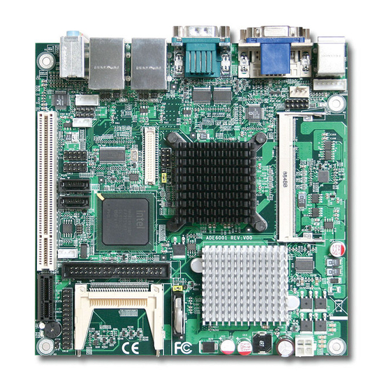
WADE-8170 ® Intel N270 945GSE Mini ITX Quick Installation Guide Rev. 0.2 2009/01/14 P/N: 602C002600102... -
Page 2: Table Of Contents
WADE-8170 Quick Installation Guide Table of Content Introduction.........................3 Description......................3 Packing Check List....................3 Hardware Configuration Setting ................4 Board Layout.......................4 Jumpers & Connectors ..................5 Jumpers/Connectors Setting................6 2.3.1 LVDS POWER SETTING (JP1)..............6 2.3.2 Clear CMOS (JP2) ..................6 2.3.3 Auto Power On (JP3) ..................6 2.3.4... -
Page 3: Introduction
DC-in 12V, 15-24V through 4-pin connector designed to support ATX power function, and a feature of CPU overheat protection will provide user more security and stability. Combing with these outstanding features in the Mini-ITX form factor, WADE-8170 is definitely the most excellent choice for embedded applications like Network, Point of Sales (POS), automated KIOSKs, security products, medical instruments, and gaming machines. -
Page 4: Hardware Configuration Setting
Hardware Configuration Setting This chapter gives the definitions and shows the positions of jumpers, headers and connectors. All of the configuration jumpers on WADE-8170 are in the proper position. The default settings shipped from factory are marked with an asterisk ( ). -
Page 5: Jumpers & Connectors
WADE-8170 Quick Installation Guide Jumpers & Connectors JUMPERS FUNCTION REMARK LVDS POWERSETTING 1 x 3 header RTC CMOS clear select 1 x 3 header Auto Power On 1 x 2 header CONNECTORS FUNCTION REMARK COM 1 2 RS-232 Serial Port Connector... -
Page 6: Jumpers/Connectors Setting
WADE-8170 Quick Installation Guide Jumpers/Connectors Setting 2.3.1 LVDS POWER SETTING (JP1) 2.3.2 Clear CMOS (JP2) PIN No. Description PIN No. Description 3.3V Power Normal operation 5V Power Clear CMOS 2.3.3 Auto Power On (JP3) 2.3.4 COM1&2 RS-232 Serial Port Connector (CN1) PIN No. -
Page 7: Usb 0 1+100/Giga Lan Connector (Cn4)
WADE-8170 Quick Installation Guide 2.3.7 USB 0 1+100/Giga LAN Connector (CN4) 2.3.8 USB 2 3+100/Giga LAN Connector (CN5) Description PIN No. PIN No. Description Description PIN No. PIN No. Description USB2- VCC5V USB0- VCC5V USB0+ USB2+ USB3- VCCV USB1- VCCV... -
Page 8: Usb 4 5 Connector (Cn10)
WADE-8170 Quick Installation Guide 2.3.13 USB 4 5 Connector (CN10) 2.3.14 LVDS Connector (CN11) PIN No. Description Description PIN No. Description VCC5 V VCC5 V USB4- LVDS_YAM0 USB4+ LVDS_YAP0 USB5- USB5+ LVDS_YAM2 Ground LVDS_YAP2 Ground LVDS_YAM1 LVDS_YAP1 LVDS_CLKBM LVDS_CLABP +12V... -
Page 9: Front Panel System Connector (Cn18)
WADE-8170 Quick Installation Guide PDIOW- Ground PDIOR- Ground PIORDY Ground PDDACK- Ground INTP PDA1 P66DET PDA0 PDA2 PDCS-1 PDCS-3 IDEACTP- Ground 2.3.19 Front Panel System Connector (CN18) 2.3.20 DC IN ATX Connector (CN19) Description PIN No. PIN No. Description Description PIN No.


Need help?
Do you have a question about the WADE-8170 and is the answer not in the manual?
Questions and answers