
Related Manuals for Portwell WADE-8071


Summary of Contents for Portwell WADE-8071
- Page 1 WADE-8071 Mini-ITX Board User's Manual Version 1.0 Copyright © Portwell, Inc., 2009. All rights reserved. All other brand names are registered trademarks of their respective owners.
-
Page 2: Table Of Contents
3.4 Clear CMOS Operation....................... 3-3 3.5 WDT Function..........................3-4 3.6 GPIO .............................. 3-5 3.6.1 Pin assignment........................3-5 3.6.2 WADE-8071 GPIO Programming Guide ............... 3-6 3.6.3 Example ..........................3-7 Chapter 4 BIOS Setup Information....................4-1 4.1 Entering Setup..........................4-1 4.2 Main Menu ........................... 4-2 4.3 Standard CMOS Setup Menu .................... -
Page 3: How To Use This Manual
Portwell may make supplement or change in the products described in this document at any time. Updates to this manual, technical clarification, and answers to frequently asked questions will be shown on the following web site : http://www.portwell.com.tw/... -
Page 4: Chapter 1 System Overview
IO interfaces that can supply various USB and COM devices. WADE-8071 supports SO-DIMM memory slot for DDR2 SDRAM up to 2GB, and comes with PS/2 Keyboard and Mouse header, 2 x RS232, 2 x SATA, 1 x IDE, 1 x Gigabit Ethernet, 6 x USB2.0 ports. -
Page 5: Product Specification
Watchdog Timer - Support WDT function through software programming for enable/disable and interval setting - Generate system reset On-board VGA - Intel 945GSE Integrated GMA950 Graphics device - Intel DVMT 3.0 supports up to 128MB video memory WADE-8071 User’s Manual... - Page 6 Configuration: System Configuration CPU Type Intel® Atom™ N270 1.60GHz (133*12) L2:512K FSB:533MHz SBC BIOS Portwell, Inc. WADE-8071 BIOS Rev.: R1.00.W0.T0 (02192009) Memory Transcend DDR2 533MHz 2GB (Micron 7WE17 D9HNL) VGA Card Onboard Mobile Intel® 845 Express Chipset Family VGA Driver Mobile Intel®...
- Page 7 Full Loading Full Loading Item Power ON 10Min 30Min System +12V 1.25A 1.80A 1.85A USB Loading Test 5.2 V/ 0.6 A Operating Temperature: 0°C ~ 55°C Storage Temperature: -20°C ~ 80°C Relative Humidity: 5% ~ 90%, non-condensing WADE-8071 User’s Manual...
-
Page 8: Mechanical Drawing
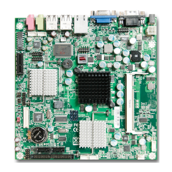
System Overview 1.3.1 Mechanical Drawing [TOP side] WADE-8071 User’s Manual... -
Page 9: Bottom Side
System Overview [Bottom side] WADE-8071 User’s Manual... -
Page 10: System Architecture
System Overview System Architecture All of details operating relations are shown in WADE-8071 series System Block Diagram WADE-8071 System Block Diagram WADE-8071 User’s Manual... -
Page 11: Chapter 2 Hardware Configuration
Hardware Configuration This chapter gives the definitions and shows the positions of jumpers, headers and connector. All of the configuration jumpers on WADE-8071 are in the proper position. The default settings are indicated with a star sign ( ). Jumper Setting In general, jumpers on the single board computer are used to select options for certain features. - Page 12 JP8 : Pin Assignments Signal Signal Signal PIN No. PIN No. PIN No. Description Description Description +12V VDDVLDS_IN VCC3 Note: Wrong voltage selection may damage the LVDS panel. Please survey LVDS panel’s VDD before setup this jumper setting. WADE-8071 User’s Manual...
-
Page 13: Connector Allocation
Wafer 2mm Line_out Pin HDR Wafer 2mm KB/MS Pin HDR GPIO Pin HDR 5P*2 Front Panel Pin HDR JP11 BACK LIGHT PWR Connector Wafer 2mm JP12/JP14 External +5V/+12V Pin HDR Wafer 2mm JP13 External USB Pin HDR WADE-8071 User’s Manual... - Page 14 CASEOPEN Signal Ground J12 : LVDS Connector PIN1 PIN No. Signal Description PIN No. Signal Description LCD1DO0+ LCD1DO0- LCD1DO1+ LCD1DO1- LCD1DO2+ LCD1DO2- LCD1DO3+ LCD1DO3- LCD1CLK+ LCD1CLK- LCD2DO0+ LCD2DO0- LCD2DO1+ LCD2DO1- LCD2DO2+ LCD2DO2- LCD2DO3+ LCD2DO3- LCD2CLK+ LCD2CLK- LCLK1 LDATA1 WADE-8071 User’s Manual...
- Page 15 JP1 : COM Serial Port PIN1 PIN No. Signal Description Ground Ground JP2 : MIC Pin HDR PIN1 PIN No. Signal Description MIC_L Ground MIC_R Ground JP3 : LINE_OUT Pin HDR PIN1 PIN No. Signal Description LINE_OUT_L Ground LINE_OUT_R Ground WADE-8071 User’s Manual...
- Page 16 PIN No. Signal Description PIN No. Signal Description GPIO0 GPIO4 GPIO1 GPIO5 GPIO2 GPIO6 GPIO3 GPIO7 Ground Note: All General Purpose I/O ports can only apply to standard TTL ± 5% signal level (0V/5V), and each Fan. WADE-8071 User’s Manual...
- Page 17 PIN No. Signal Description 5VSBY through 330 ohm PWRLED 5VSBY through 1k ohm PWR_ON +5V through 150 ohm RESET# HDD_LED# Ground JP11 : BACL LIGHT PWR Pin HDR PIN1 PIN No. Signal Description BACK LIGHT ENABLE +12V WADE-8071 User’s Manual...
- Page 18 PIN1 PIN No. Signal Description +12V Ground Ground JP13 : External USB Pin HDR PIN1 PIN No. Signal Description PIN No. Signal Description 5V Dual 5V Dual USB- USB- USB+ USB+ Ground Ground Key( no pin ) WADE-8071 User’s Manual...
-
Page 19: Chapter 3 System Installation
Main Memory WADE-8071 provides 1 x 200-pin SO-DIMM sockets which supports 667/533 DDR2-SDRAM as main memory, Non-ECC (Error Checking and Correcting), non-register functions. The maximum memory size can be up to 2GB capacity. -
Page 20: Installing The Single Board Computer
3.3.2 Chipset Component Driver The chipset on WADE-8071 is a new chipset that a few old operating systems might not be able to recognize. To overcome this compatibility issue, for Windows Operating Systems such as Windows 2000 /XP, please install its INF before any of other Drivers are installed. -
Page 21: Realtek Gigabit Ethernet Controller
System Installation Drivers Support Please find Springdale GMCH driver in the WADE-8071 CD-title. Drivers support Windows-2000, Windows XP. 3.3.4 Realtek Gigabit Ethernet Controller Drivers Support Please find Realtek RTL8111C LAN driver in /Ethernet directory of WADE-8071 CD-title. The drivers support Windows 2000 /XP. -
Page 22: Wdt Function
WADE-8071 allows users control WDT through dynamic software programming. The WDT starts counting when it is activated. It sends out a signal to system reset or to non-maskable interrupt (NMI), when time-out interval ends. -
Page 23: Gpio
0xaa); GPIO The WADE-8071 provides 8 programmable input or output ports that can be individually configured to perform a simple basic I/O function. Users can configure each individual port to become an input or output port by programming register bit of I/O Selection. -
Page 24: Wade-8071 Gpio Programming Guide
3.6.2 WADE-8071 GPIO Programming Guide There are 8 GPIO pins on WADE-8071. These GPIO pins are from SUPER I/O (W83627GH-AW) GPIO pins, and can be programmed as Input or Output direction. JP5 pin header is for 8 GPIO pins and its pin assignment as following : JP5_Pin1=GPIO0:from SUPER I/O_GPIO10 with Ext. -
Page 25: Example
System Installation How to access W83627HG CR? In WADE-8071, the EFER = 002Eh, and EFDR = 002Fh. EFER and EFDR are 2 IO ports needed to access W83627HG-AW CR. EFER is the Index Port, EFDR is the Data Port. CR index number needs to be written into EFER first, Then the data will be read/written from/to EFDR. - Page 26 Set_CFG2(0xF1, 0xEF); /* GP14 of Superio2 -> ~GP10 of Superio2 */ Set_CFG2(0x07, 0x07); /* Select logic device 07 of Superio2*/ d2 = Get_CFG2(0xF1); /* get GPIO Port 2 data */ if (d2 == 0xEE ) printf("\n GPIO14->10 test ok"); else printf("\n GPIO14->10 test fail "); WADE-8071 User’s Manual...
-
Page 27: Chapter 4 Bios Setup Information
Chapter 4 BIOS Setup Information WADE-8071 is equipped with the AWARD BIOS stored in Flash ROM. These BIOS has a built-in Setup program that allows users to modify the basic system configuration easily. This type of information is stored in CMOS RAM so that it is retained during power-off periods. -
Page 28: Main Menu
BIOS Setup Information Main Menu Once you enter WADE-8071 AWARD BIOS CMOS Setup Utility, a Main Menu is presented. The Main Menu allows user to select from eleven setup functions and two exit choices. Use arrow keys to switch among items and press <Enter> key to accept or bring up the sub-menu. -
Page 29: Standard Cmos Setup Menu
Change the day, month, year and century Time hh:mm:ss Change the internal clock IDE Channel 0 Master Options are in its sub Press <Enter> to enter next page for IDE Channel 0 menu detail hard druve settings Slave IDE Channel 1 Master WADE-8071 User’s Manual... -
Page 30: Ide Adaptors Setup Menu
↑↓→←: Move Enter: Select +/-/PU/PD: Value F10: Save ESC: Exit F1: General Help F5: Previous Values F6: Fail-Safe Defaults F7: Optimized Defaults Note: The oblique items are meaning base on what kind of storage device user employs. WADE-8071 User’s Manual... - Page 31 Set the number of cylinders for hard disk Head Min=0, Max=255 Set the number of read/write heads Precomp Min=0, Max=65535 **** Warning: Setting a value of 65535 means no hard disk Landing zone Min=0, Max=65535 **** Sector Min=0, Max=255 Number of sectors per track WADE-8071 User’s Manual...
-
Page 32: Advanced Bios Features
Limit CPUID MaxVal [Disabled] Menu Level C1E Function [Auto] CPU C1E Function Select Execute Disable Bit [Enabled] ↑↓→←: Move Enter: Select +/-/PU/PD: Value F10: Save ESC: Exit F1: General Help F5: Previous Values F6: Fail-Safe Defaults F7: Optimized Defaults WADE-8071 User’s Manual... - Page 33 Enabled warning message to appear when anything attempts to access the boot sector or hard disk partition table. No warning message will appear when anything attempts to access Disabled the boot sector or hard disk partition table. WADE-8071 User’s Manual...
- Page 34 The choice: Disabled, Enabled. ※Typematic Rate (Chars/sec) The rate is which character repeats when you hold down a key. The choice: 6, 8, 10, 12, 15, 20, 24, and 30. (Default 6) WADE-8071 User’s Manual...
- Page 35 Select OS/2 only if you are running OS/2 operating system with greater than 64MB of RAM on the system. The choice: Non-OS2, OS2. Report No FDD for WIN 95 The choice: No, Yes. Small Logo (EPA) Show The choice: Enabled, Disabled. WADE-8071 User’s Manual...
-
Page 36: Advanced Chipset Features
↑↓→←: Move Enter: Select +/-/PU/PD: Value F10: Save ESC: Exit F1: General Help F5: Previous Values F6: Fail-Safe Defaults F7: Optimized Defaults System BIOS Cacheable. The choice: Enabled, Disabled. Memory Hole At 15-16M The choice: Enabled, Disabled. WADE-8071 User’s Manual 4-10... -
Page 37: Dvmt Mode
DVMT/FIXED Memory Size The choice: 64MB, 128MB, 224MB. Boot Display The choice: CRT, LVDS, CRT+LVDS, DVI, TV, CRT+DVI, CRT+TV. Panel Scaling The choice: Auto, On, Off. Panel Number The choice: 640x480 18bits, 800x600 18bits, 1024x768 18bits, 1280x1024 24bits. WADE-8071 User’s Manual 4-11... -
Page 38: Integrated Peripherals
F7: Optimized Defaults IDE HDD Block Mode If IDE hard drive supports block mode select Enabled for automatic detection of the optimal number of block read/writes per sector the drive can support. The choice: Enabled, Disabled. WADE-8071 User’s Manual 4-12... - Page 39 Max. of 2 IDE drives in each channel. [Enhanced Mode]: Enable both SATA and PATA. Max. of 4 IDE drives are supported. [SATA only]: Only enable SATA. The Choice: Disabled, Auto, Combined Mode, Enhanced Mode, SATA Only. PATA IDE Mode The Choice: Secondary. WADE-8071 User’s Manual 4-13...
- Page 40 [Enabled] or [Disabled] Enhanced host controller interface for universal serial bus. The choice: Enabled, Disabled. USB Keyboard/Mouse Function [Enabled] or [Disabled] Legacy support of USB keyboard or mouse. The choice: Disabled, Enabled. Azalia/AC97 Audio Select [Enabled] or [Disabled] AC97 Audio controller. WADE-8071 User’s Manual 4-14...
- Page 41 Low rate for receiving / Low rate for transmitting IR Transmission Delay This option will be available when IR is enabled. The choice: Enabled, Disabled. UR2 Duplex Mode The available choices are full duplex mode and half duplex mode The choice: Full, Half. WADE-8071 User’s Manual 4-15...
- Page 42 Watch Dog Timer Select This BIOS testing option is able to reset the system according to the selected table. The choice: Disabled, 10 Sec, 20 Sec, 30 Sec, 40 Sec, 1 Min, 2 Min, and 4 Min. WADE-8071 User’s Manual 4-16...
-
Page 43: Power Management Setup
ACPI Function This item allows you to enable/disable the Advanced Configuration and Power Management (ACPI). The choice: Enabled, Disabled. ACPI Suspend Type To decide which ACPI suspend mode to use. The choice: S1 (POS), S3 (STR). WADE-8071 User’s Manual 4-17... - Page 44 This item allows users to set the time to remove the power after the power button is pressed. The choice: Instant-Off, Delay 4 Sec. Power On by Ring When select “Enabled”, a system that is at soft-off mode will be alert to Wake-On-Modem signal. The choice: Enabled, Disabled. WADE-8071 User’s Manual 4-18...
- Page 45 The choice: Enabled, Disabled. PCI PIRQ[A-D]# This option can be used to detect PCI device activities. If they are activities, the system will go into sleep mode. The choice: Enabled, Disabled. WADE-8071 User’s Manual 4-19...
-
Page 46: Pnp/Pci Configurations
BIOS can automatically configure the entire boot and plug and play compatible devices. If set to Auto, IRQ DMA and memory base address fields can not be selected, since BIOS automatically assigns them. The choice: Auto (ESCD), Manual. WADE-8071 User’s Manual 4-20... -
Page 47: Pc Health Status
3.28 V +3.3 V 3.32 V +12 V 12.22 V + 5 V 5.21 V ↑↓→←: Move Enter: Select +/-/PU/PD: Value F10: Save ESC: Exit F1: General Help F5: Previous Values F6: Fail-Safe Defaults F7: Optimized Defaults WADE-8071 User’s Manual 4-21... -
Page 48: Default Menu
Type the password, up to eight characters in length, and press <Enter>. The password typed now will clear any previously entered password from CMOS memory. You will be asked to confirm the password. Type the password again and WADE-8071 User’s Manual 4-22... -
Page 49: Exiting Selection
Pressing <Enter> on this item asks for confirmation: Quit Without Saving (Y/N)? N This allows user to exit Setup without storing in CMOS any change. The previous selections remain in effect. This exits the Setup utility and restarts your computer. WADE-8071 User’s Manual 4-23... -
Page 50: Chapter 5 Troubleshooting
Chapter 5 Troubleshooting This chapter provides a few useful tips to quickly get WADE-8071 running with success. As basic hardware installation has been addressed in Chapter 2, this chapter will primarily focus on system integration issues, in terms of BIOS setting, and OS diagnostics. -
Page 51: Bios Setting
BIOS setting back to the initial factory configuration. It is recommended to do this so you can be sure the system is running with the BIOS setting that Portwell has highly endorsed. As a matter of fact, users can load the default BIOS setting any time when system appears to be unstable in boot up sequence. -
Page 52: Ordering Setting
It is then very easy to find out which IRQ resource is ready for additional peripherals. If IRQ resource is not enough, please disable some devices listed above to release further IRQ numbers. Ordering Setting PER-4110R One slot PCI-E x1 to PCI-Ex1 WADE-8071 User’s Manual... -
Page 53: Faq
Please visit our technical web site at http://www.portwell.com.tw For additional technical information, which is not covered in this manual, you can mail to tsd@mail.portwell.com.tw or you can also send mail to our sales, they wull be very delighted to forward them to us. WADE-8071 User’s Manual... - Page 54 Program Area 0F6C-9EFF 574K [Available] = Conventional memory ends at 636K = 9F00-9FBF Extended BIOS Area 9FC0-9FFF Unused A000-AFFF VGA Graphics B000-B7FF Unused B800-BFFF VGA Text C000-CEBF Video ROM CEC0-EFFF 133K Unused F000-FFFF System ROM First 64K Extended WADE-8071 User’s Manual...
- Page 55 Usable IRQ IRQ 10 [Unassigned] Usable IRQ IRQ 11 [Unassigned] Usable IRQ IRQ 12 System ROM IBM Mouse Event IRQ 13 System ROM Coprocessor Error IRQ 14 System ROM Hard Disk Event IRQ 15 [Unassigned] Usable IRQ WADE-8071 User’s Manual...
Need help?
Do you have a question about the WADE-8071 and is the answer not in the manual?
Questions and answers