
Subscribe to Our Youtube Channel
Related Manuals for Portwell WADE-8078


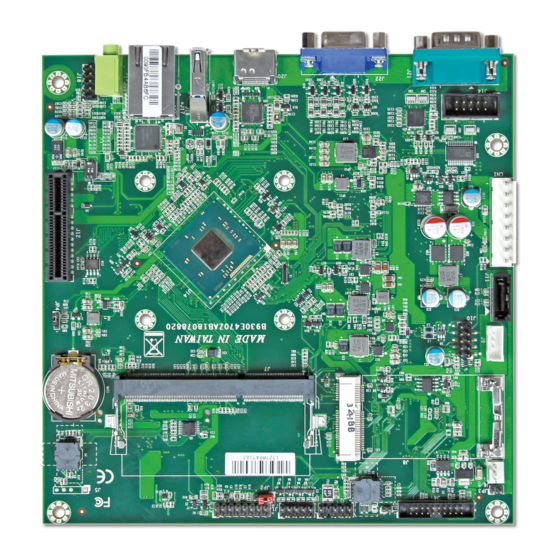
Summary of Contents for Portwell WADE-8078
- Page 1 WADE-8078 Mini-ITX Board User's Manual Version 1.0 Copyright © Portwell, Inc., 2012. All rights reserved. All other brand names are registered trademarks of their respective owners.
-
Page 2: Table Of Contents
Preface Table of Contents How to Use This Manual Chapter 1 System Overview.......................1-1 1.1 Introduction ....................... 1-1 1.2 Check List......................1-1 1.3 Product Specification..................1-2 1.3.1 Mechanical Drawing................1-4 1.4 System Architecture..................1-6 Chapter 2 Hardware Configuration ...................2-1 2.1 Jumper Setting ....................2-1 2.2 Connector Allocation.................. -
Page 3: How To Use This Manual
Preface How to Use This Manual The manual describes how to configure your WADE-8078 system board to meet various operating requirements. It is divided into five chapters, with each chapter addressing a basic concept and operation of Single Host Board. -
Page 4: Chapter 1 System Overview
Built with Intel’s latest chipset, WADE-8078 series take advantage of the Intel® Atom™ Valleyview E38XX series processors. WADE-8078 has lots of features, also features one SATA connectors (SATA 3Gb/s) storage specification , one DDR3 SO-DIMM memory slot for DDR3L ECC SDRAM up to 4GB, support total 3 USB ports (1x USB3.0 on REAR I/O,2x USB2.0... -
Page 5: Product Specification
On-board Ethernet LAN One Gigabit Ethernet (10/100/1000 Mbits/sec) LAN ports High Drive GPIO One pin-header for 8 bit GPIO System Monitoring Feature Monitor system temperature and major power sources. Outline Dimension (L x W) 170mm(6.69’’) x 170mm(6.69’’) Power Requirements WADE-8078 User’s Manual... -
Page 6: Vga Driver
System Overview Configuration CPU Type Genuine Intel® CPU@ 1.91 GHz Atom L3:2M Bytes SBC BIOS Portwell, Inc. WADE-8078 BIOS ( 30903T00 ) EVALUATION COPY ECC Memory WARIS DDR3L SO-DIMM 1333 4GB*1 (hynix H5TC2G83EFR) VGA Card Onboard Intel(R) HD Graphics VGA Driver Intel(R) HD Graphics Version:10.18.10.3266... -
Page 7: Mechanical Drawing
System Overview 1.3.1 Mechanical Drawing WADE-8078 User’s Manual... - Page 8 System Overview WADE-8078 User’s Manual...
-
Page 9: System Architecture
System Overview System Architecture All of details operating relations are shown in WADE-8078 System Block Diagram. WADE-8078 System Block Diagram WADE-8078 User’s Manual... -
Page 10: Chapter 2 Hardware Configuration
Hardware Configuration This chapter gives the definitions and shows the positions of jumpers, headers and connectors. All of the configuration jumpers on WADE-8078 are in the proper position. The default settings shipped from factory are marked with an asterisk (♣). - Page 11 Hardware Configuration Figure 2-1 WADE-8078 Jumper and Connector Locations WADE-8078 User’s Manual...
- Page 12 Signal Function 1-2 short 2-3 short +3.3V JP5: BIOS Select PIN No Signal Function 1-2 short SPI Flash 2-3 short CFEX BIOS JP6: Clear CMOS PIN No Signal Function Function 1-2 short Normal 2-3 short Clear CMOS WADE-8078 User’s Manual...
- Page 13 Key( no pin ) Ground Ground +5V_Dual +5V_Dual Mouse Clock Keyboard Clock J3:Front Panel System Connector Pin No. Signal Description Pin No. Signal Description PWR_LED(+) Speaker(+) PWR_LED(-) J17 LAN_ACT(+) J17 LAN_LINK(-) Speaker(-) Power Button HDD_LED(+) Rest HDD_LED(-) WADE-8078 User’s Manual...
- Page 14 Pin No. Signal Description TPM Clock Ground LFRAME# PLTRST# LAD3 LAD2 +3.3V LAD1 LAD0 Ground SMB_CLK SMB_DATA J6: System FAN Connector PIN No Signal Function +12V SENSE J9: SATA Power PIN No Signal Function +12V Ground Ground WADE-8078 User’s Manual...
- Page 15 Receive Data Transmit Data Data Terminal Ready Data Set Ready Request To Send Clear To Send Ring Indicator J18: Audio MIC/Line-in/Line-out Connector Pin No. Signal Description Pin No. Signal Description MIC_L Line_in_L Ground Line_in_R Line_out_L Ground Line_out_R MIC_R WADE-8078 User’s Manual...
- Page 16 Hardware Configuration CN1: 8 Pin ATX Connector PIN No Signal Description +5Vsb +12V PS_ON# Ground Ground Ground SW1: ATX Detect &BIOS Recovery Switch Signal Description ATX Detect AT Mode ATX Mode BIOS Recovery Enable Disable WADE-8078 User’s Manual...
- Page 17 RTS (Request to Send) TXD (Transmit Data) CTS (Clear to Send) DTR (Data Terminal Ready) RI (Ring Indicator) GND (Ground) J22: VGA Connector Pin No. Signal Description Pin No. Signal Description CRT_R CRT_G CRT_B VGA_DDCDA CRT_HS CRT_VS VGA_DDCCL WADE-8078 User’s Manual...
-
Page 18: Connector Allocation
HDMI Connector COM 1 Serial Port Connector Support RS-232/422/485 VGA Connector CFEX Connector Watch Dog Timer Enable GPIO Voltage Select BIOS Select Clear CMOS ATX Detect &BIOS Recovery Switch EC EEPROM Socket BIOS Socket Bay Trail-I CPU WADE-8078 User’s Manual... -
Page 19: Chapter 3 System Installation
Step 1 : Check all jumpers setting on proper position Step 2 : Install and configure CPU and memory module on right position Step 3 : Place WADE-8078 into the dedicated position in the system Step 4 : Attach cables to existing peripheral devices and secure it WARNING Please ensure that SBC is properly inserted and fixed by mechanism. -
Page 20: Chipset Component Driver
3.3.1 Chipset Component Driver WADE-8078 uses state-of-art Intel® BayTrail-I chipset. It’s a new chipset that some old operating systems might not be able to recognize. To overcome this compatibility issue, for Windows Operating Systems such as Windows 8, please install its INF before any of other Drivers are installed. -
Page 21: Wdt Function
#define WDT_MODE 0x06 // WDT Select mode. #define WDT_MIN 0x07 // Minute mode counter #define WDT_SEC 0x08 // Second mode counter // Use port 62 and port 66 to access EC command / data. static int IBF_Check() WADE-8078 User’s Manual... - Page 22 Read_EC (unsigned char address) unsigned char data; IBF_Check (); outportb (EC_CMD, EC_CMD_READ); IBF_Check (); outportb (EC_DATA, address); OBF_Check(); data = inportb (EC_DATA); return data; void EC_WDT_Trigger () /* WDT Counter */ Write_EC (WDT_SEC, 0x05); WADE-8078 User’s Manual...
-
Page 23: Gpio
0x2B // GPIO Direction (Input/Output) Reg. #define GPIO_DATA 0x2C // GPIO High/Low Reg. // Use port 62 and port 66 to access EC command / data. static int IBF_Check() unsigned char IBF_status; pw_udelay (20); // delay 20 us WADE-8078 User’s Manual... - Page 24 = inportb (EC_DATA); return data; int main () unsigned char d2; printf("\n\n"); printf("WADE-8078 GPIO TEST Program v1.0\n"); printf("Please short the following pins with 2.54mm-pitched jumper on JP8\n"); printf("PIN 1,3,5,7 is output ; PIN 2,4,6,8 is input\n"); WADE-8078 User’s Manual...
- Page 25 ((d2 & 0x40) == 0) printf ("GPIO72->GPIO76 test ok !! (pull low)\n"); else printf ("GPIO72->GPIO76 test fail (pull high)\n"); if ((d2 & 0x80) == 0) printf ("GPIO73->GPIO77 test ok !! (pull low)\n"); else printf ("GPIO73->GPIO77 test fail (pull high)\n"); return 0; WADE-8078 User’s Manual...
-
Page 26: Chapter 4 Bios Setup Information
Chapter 4 BIOS Setup Information WADE-8078 is equipped with the Phoenix BIOS stored in Flash ROM. These BIOS has a built-in Setup program that allows users to modify the basic system configuration easily. This type of information is stored in CMOS RAM so that it is retained during power-off periods. -
Page 27: Main
The date format is <Day>, <Month> <Date> <Year>. Use [+] or [-] to configure system Date. System Time View or set system time The time format is <Hour> <Minute> <Second>. Use [+] or [-] to configure system Time. WADE-8078 User’s Manual... - Page 28 BIOS Setup Information System Information Display System Information Boot Features Select Boot features WADE-8078 User’s Manual...
- Page 29 Choices: Disable, Enable. Console Redirection Enable/Disable Universal Console Redirection Choices: Disable, Enable. Allow Hotkey in S4 Resume Enable hotkey detection when system resuming from Hibernate state Choices: Disable, Enable. WADE-8078 User’s Manual...
- Page 30 BIOS Setup Information Error Manager Display Error Manager Log information. View Error Manager Log Display Error Manager Log information Clear Error Manager Log Clear Error Manager Log. WADE-8078 User’s Manual...
-
Page 31: Advanced
BIOS Setup Information Advanced Setup Warning: Setting items on this screen to incorrect values may cause system to malfunction! WADE-8078 User’s Manual... - Page 32 Disabled for Windows XP Choices: Disable, Enable. Bi-directional PROCHOT# When a processor thermal sensor trips (either core), the PROCHOT# will be driven If bi-direction is enabled, external agents can drive PROCHOT# to throttle the processor Choices: Disable, Enable. WADE-8078 User’s Manual...
- Page 33 System Power Options Intel® SpeedStep™ Allows more than two frequency ranges to be supported Choices: Disabled, Enabled. Boot performance mode Select the performance state that the BIOS will set before OS handoff Choices: Max Performance, Max Battery. WADE-8078 User’s Manual...
- Page 34 This option controls the Max C State that the processor will support Choices: C7, C6, C4, C1. Uncore Configuration GOP Configuration GOP Driver Enable GOP Driver will unload VBIOS; Disable it will load VBIOS Choices: Enable, Disable. WADE-8078 User’s Manual...
- Page 35 384M,416M, 448M, 480M, 512M. Spread Spectrum clock Enable clock chip Spread Spectrum feature Choices: Disable, Enable. IGD – LCD Control Force Lid States For test: Force to set lid status as on or off Choices: OFF, ON. WADE-8078 User’s Manual 4-10...
- Page 36 Select the LCD Panel scaling option used by Internal Graphic device Choices: Auto, Centering, Stretching. System Component PMIC Congfiguration PNP Setting Select PNP setting mode, Disable, Performance, Power or Power&Performance mode. Choices: Disable, Performance, Power, Power&Performance WADE-8078 User’s Manual 4-11...
- Page 37 BIOS Setup Information South Cluster Configuration PCI Express Configuration PCI Express Configuration Settings WADE-8078 User’s Manual 4-12...
- Page 38 Mode of operation of xHCI controller Choices: Smart Auto, Auto, Enable, Disable. USB OTG Support Enable/Disable USB OTG Support Choices: Disable, PCI Mode, ACPI Mode. EHCI Controller Control each of the USB ports (0~9) disabling Choices: Enable, Disable. WADE-8078 User’s Manual 4-13...
- Page 39 Auto = Azalia will be enabled if present. Disable otherwise Choices: Disable, Enable. Azalia VCi Enable Enable/ Disable Virtual Channel 1 of Audio Controller Choices: Disable, Enable. Azalia Docking Support Enable Enable/ Disable Virtual Channel 1 of Audio Controller Choices: Disable, Enable. WADE-8078 User’s Manual 4-14...
- Page 40 Enables or Disables the Chipset SATA Controller. The Chipset SATA controller supports the 2 black internal SATA ports (up to 3Gb/s supported per port). Choices: Enable, Disable. SATA Test Mode Test Mode Enable/Disable Choices: Enable, Disable. WADE-8078 User’s Manual 4-15...
- Page 41 If enabled, SATA port 0/1 will be reported as Hot Plug capable. Choices: Enable, Disable. LPSS & SCC Configuration LPSS & SCC Mode Choices: ACPI Mode, PCI Mode. SCC eMMC Support Choices: Disable, Enable. SCC SDIO Support Choices: Disable, Enable. WADE-8078 User’s Manual 4-16...
- Page 42 LPSS DMA #1/#2 Support Choices: Disable, Enable. LPSS I2C #1~7 Support Choices: Disable, Enable. LPSS HSUART #1/#2 Support Choices: Disable, Enable. LPSS PWM #1/#2 Support Choices: Disable, Enable. LPSS SPI Support Choices: Disable, Enable. Miscellaneous Configuration Enable/Disable Misc. Features WADE-8078 User’s Manual 4-17...
- Page 43 Choices: S0 State, S5 State. Clock Spread Spectrum Enable Clock Chip’s Spread Spectrum feature. Choices: Disable, Enable. UART Interface Selection Select which UART interface to use. Choices: Intermal UART, SuperIO UART. SMBIOS Event Log Manage SMBIOS Event Log. WADE-8078 User’s Manual 4-18...
- Page 44 Event Log Enable/Disable Event Log. Choices: Disable, Enable. View SMBIOS event log View SMBIOS event log Mark SMBIOS events as read Mark SMBIOS events as read. Marked SMBIOS events won’t bedisplayed. Clears SMBIOS events Clears SMBIOS events. WADE-8078 User’s Manual 4-19...
-
Page 45: Others
BIOS Setup Information Others SIO Configuration WADE-8078 User’s Manual 4-20... -
Page 46: Hardware Monitor
COM1 Configuration Select COM1 Configuration. Choices: RS-232, RS-422, RS-285. Watch Dog Timer Select Choices: Disable, 15 secs, 30 secs, 1 min, 2 mins, 3 mins. Power Control Choices: Former State, Always On, Always Off. Hardware Monitor WADE-8078 User’s Manual 4-21... -
Page 47: Apm Configuration
BIOS Setup Information APM Configuration Power On By RTC Alarm Choices: Disable, Enable. Wake on LAN1 Choices: Disable, Enable. Wake up by Ring Choices: Disable, Enable. PCI Subsystems Settings PCI, PCI-X and PCI Express Settings. WADE-8078 User’s Manual 4-22... -
Page 48: Security
Press Enter to type Supervisor Hint String. Set User Password Set or clear the User account’ password. Supervisor Hint String Press Enter to type User Hint String. Min. password length Set the minimum number of characters for password (1-20). WADE-8078 User’s Manual 4-23... -
Page 49: Boots
Boot Priority Order Keys used to view or configure devices: ↑ and ↓ arrows Select a device. ‘+’ and ‘-‘move the device up or down. ‘Shift + 1’ enabled or disables a device. ‘Del’ deletes an unprotected device. WADE-8078 User’s Manual 4-24... -
Page 50: Security
Load Setup Defaults Equal to F9. Load standard default values. Discard Changes Load the original value of this boot time. Not the default Setup value. Save Changes Save all changes of all menus, but do not reset system. WADE-8078 User’s Manual 4-25... -
Page 51: Save & Exit
If it doesn’t have boot device, it will return to BIOS setup menu. If you want to know the shell command, you can visit the Intel official hyperlink as below. http://software.intel.com/en-us/articles/uefi-shell/#Internal_EFI_Shell_Commands WADE-8078 User’s Manual 4-26... -
Page 52: Chapter 5 Troubleshooting
Chapter 5 Troubleshooting This chapter provides a few useful tips to quickly get WADE-8078 running with success. As basic hardware installation has been addressed in Chapter 2, this chapter will primarily focus on system integration issues, in terms of BIOS setting, and OS diagnostics. -
Page 53: Bios Setting
To make sure that you have a successful start with WADE-8078, it is recommended, when going with the boot-up sequence, to hit “F2” key and enter the BIOS setup menu to tune up a stable BIOS configuration so that you can wake up your system far well. - Page 54 Troubleshooting Question: How to update the BIOS file of the WADE-8078? Answer: 1. Please visit web site of the Portwell download center as below hyperlink http://www.portwell.com.tw/support/download_center.php But you must register an account first. (The E-Mail box should be an existing Company email address that you check regularly.) http://www.portwell.com.tw/member/newmember.php...
- Page 55 Troubleshooting 6. Insert your USB pen drive in USB port of the WADE-8078 board and power-on. 7. Boot to EFI-Shell mode then input the “fs0:” command to switch to the root of the USB pen drive. 8. Type the”update” command to start flash BIOS processes.
Need help?
Do you have a question about the WADE-8078 and is the answer not in the manual?
Questions and answers