
Related Manuals for Portwell WADE-8173-J6412


Summary of Contents for Portwell WADE-8173-J6412
- Page 1 WADE-8173-J6412 WADE‐8173‐J6412 Industrial Mini‐ITX Board Version 1.0 Copyright © Portwell 2022 WADE-8173-J6412 User's Guide...
- Page 2 WADE-8173-J6412 Revision History R1.0 Preliminary Copyright © Portwell 2022 WADE-8173-J6412 User's Guide...
-
Page 3: Table Of Contents
6.3 Installing the Single Board Computer ................................. 55 6.3.1 Chipset Component Driver ..................................56 6.3.2 Intel® UHD Graphics ..................................... 56 6.3.3 RealtekRTL8111H Gigabit Ethernet Controller ............................56 7 BIOS Setup Items ......................................... 57 7.1 Introduction ........................................57 Copyright © Portwell 2022 WADE-8173-J6412 User's Guide... - Page 4 Troubleshooting ........................................105 8.1 Hardware Quick Installation ................................... 105 8.2 BIOS Setting ......................................... 106 8.3 FAQ ..........................................107 9 Portwell Software Service ....................................113 10 Industry Specifications ......................................114 10.1 Industry Specifications ..................................114 Copyright © Portwell 2022 WADE-8173-J6412 User's Guide...
- Page 5 Portwell provides no warranty with regard to this user’s guide or any other information contained herein and hereby expressly disclaims any implied warranties of merchantability or fitness for any particular purpose with regard to any of the foregoing. Portwell assumes no liability for any damages incurred directly or indirectly from any technical or typographical errors or omissions contained herein or for discrepancies between the product and the user’s guide.
- Page 6 Warranty”). Portwell may in its sole discretion modify its Limited Warranty at any time and from time to time. Beginning on the date of shipment to its direct customer and continuing for the published warranty period, Portwell represents that the products are new and warrants that each product failing to function properly under normal use, due to a defect in materials or workmanship or due to non conformance to the agreed upon specifications, will be repaired or exchanged, at Portwell’s option and expense.
-
Page 7: Introduction
WADE-8173-J6412 1 Introduction The WADE-8173-J6412, designed with Elkhart Lake Intel CeleronJ6412processor, features two DDR43200 MHz SO-DIMM socket equipped with up to 32GB DDR4 non-ECC memory. Celeron solution is still popular in the market of Kiosk, Panel PC, Digital Security and Digital Signage which can fulfill most of these applications; therefore, with high performance and high-end specifications, Elkhart Lake SoC is our first generationCeleron chip architecture on Mini-ITX line. -
Page 8: Specifications
Serial Ports:5x RS-232 on board &1x RS-232/422/485 on board ◆ Input/Output USB Port: 3x USB 3.2 Gen2 on rear I/O,1x USB 2.0 on rear I/O and 4x USB2.0 on board header ◆ Audio Interface: Line-In and Line-Out ◆ Copyright © Portwell 2022 WADE-8173-J6412 User's Guide... -
Page 9: Supported Operating Systems
Board size: 170mm x 170 mm ◆ Safety CE, FCC ◆ 2.1Supported Operating Systems The WADE-8173-J6412 supports the following operating systems. Windows 10* (64 bit), IoT Core(32/64bit) Wind River* 8.0 Linux Distribution(64 bit) Yocto* Tool-based Embedded Linux Distribution (64 bit) ... -
Page 10: Mechanical Dimensions
WADE-8173-J6412 2.2 Mechanical Dimensions Copyright © Portwell 2022 WADE-8173-J6412 User's Guide... - Page 11 Audio Card Realtek ALC897 Audio Driver Realtek High Definition Audio v6.0.9313.1 Chip Driver Intel ® Chipset Device Software Version: V10.1.18768.8273 USB3.0 Driver Intel USB 3.0 eXtensible Host Controller :V10.1.18768.8273 ® Power Supply 12V DC-in Copyright © Portwell 2022 WADE-8173-J6412 User's Guide...
-
Page 12: Environmental Specifications
S1(Monitor Auto Off) S3(Sleep mode) <5Watt 1.076 S5(Shut down) 0.313( ErP enable), 0.925( ErP Disable) 2.3 Environmental Specifications Storage Temperature : -20~80°C Operation Temperature : 0~60°C Storage Humidity : 5~95% Operation Humidity: 10~90% Copyright © Portwell 2022 WADE-8173-J6412 User's Guide... -
Page 13: Block Diagram
WADE-8173-J6412 3 Block Diagram Copyright © Portwell 2022 WADE-8173-J6412 User's Guide... -
Page 14: Hardware Configuration
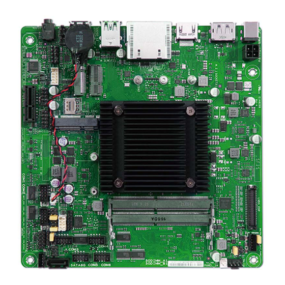
WADE-8173-J6412 4 Hardware Configuration 4.1 Jumpers and Connector This chapter indicates jumpers’, headers’ and connectors’ locations. Users may find useful information related to hardware settings in this chapter. Copyright © Portwell 2022 WADE-8173-J6412 User's Guide... -
Page 15: Jumpers Setting
4.2 Jumpers Setting For users to customize WADE-8173-J6412’s features. In the following sections, Short means covering a jumper cap over jumperpins; Open or N/C (Not Connected) means removing a jumper cap from jumper pins. Users can refer to Figure 1 for the Jumper allocations. - Page 16 Speakerheader(4‐1pinSPEAKER) 16 SystemPanelheader(10‐1pinF_PANEL) 17 COMRING/+5V/+12Vselectionjumpers(6‐pinCOM1_SEL,COM2_SEL) 18 RTCBatteryheader(2‐pinBATT_CON) 19 PS/2KeyboardandMouseheader(8‐pinKBMS_CON) 20 SDCardslot(SD_CARD) 21 ChassisIntrusionheader(4‐pinCHASSIS) 22 USB2.0headers(10‐1pinUSB_12,USB_34) 23 PCIe3.0/2.0x1slot(PCIEX1) 24 ClearRTCRAM(2‐pinCLRTC) 25 GeneralPurposeInput/outputheader(GPIO_CON) 26 FrontPanelAudioheader(10‐1pinAAFP) 27 InternalStereoSpeakerheader(2‐pinSTEREO_OUT_L,STEREO_OUT_R) 28 M.2socket3(M.2_SOCKET3) 29 M.2Wi‐Fislot 30 NanoSIMCardslot 31 MPCIecomboslot(MPCIE) Copyright © Portwell 2022 WADE-8173-J6412 User's Guide...
- Page 17 WADE-8173-J6412 1 :ATX Power connector (4-pin ATX12V) 2 :Built-in Intel® Celeron® Quad-core Processor J6412 ® The motherboard comes with an onboard Intel processor J6412. Copyright © Portwell 2022 WADE-8173-J6412 User's Guide...
- Page 18 This header supports a Trusted Platform Module (TPM) system with a Serial Peripheral Interface (SPI), allowing you to securely store keys,digitalcertificates, passwords, and data. A TPM system also helps enhance network security, protects digital identities, and ensures platform integrity. *Connector Type: 2.00mm pitch Copyright © Portwell 2022 WADE-8173-J6412 User's Guide...
- Page 19 WADE-8173-J6412 4 :DDR4 SO-DIMM slots Copyright © Portwell 2022 WADE-8173-J6412 User's Guide...
- Page 20 WADE-8173-J6412 5 :LVDS/EDP header (40-pin LVDS_EDP) Copyright © Portwell 2022 WADE-8173-J6412 User's Guide...
- Page 21 WADE-8173-J6412 6 :LVDS Panel Backlight Enable Signal Selection (BKLTEN_SEL) PIN No. Description 12V(Default) *Connector Type: 2.54mm pitch Copyright © Portwell 2022 WADE-8173-J6412 User's Guide...
- Page 22 WADE-8173-J6412 7 :LVDS Backlight Panel header (5-pin LCD_BLKT_PANEL) *Connector Type: 2.00mm pitch Copyright © Portwell 2022 WADE-8173-J6412 User's Guide...
- Page 23 WADE-8173-J6412 8 :Chassis fan header (4-pin CHA_FAN) *Connector Type: 2.54mm pitch Copyright © Portwell 2022 WADE-8173-J6412 User's Guide...
- Page 24 WADE-8173-J6412 9 :LCD Panel monitor switch header (2-pin PANEL_SW) *Connector Type: 2.54mm pitch Copyright © Portwell 2022 WADE-8173-J6412 User's Guide...
- Page 25 WADE-8173-J6412 10 :LVDS Panel VCC Power Selection jumper (6-pin VCC_PWR_SEL) PIN No. Description 1.4.5-6 1.4.5-3 1.4.5-2 3V(Default) *Connector Type: 2.54mm pitch Copyright © Portwell 2022 WADE-8173-J6412 User's Guide...
- Page 26 WADE-8173-J6412 11 :AT/ATX mode selection jumper (3-pin AT_ATX_SEL) PIN No. Description 1-2(Default) ATX mode AT mode *Connector Type: 2.54mm pitch Copyright © Portwell 2022 WADE-8173-J6412 User's Guide...
- Page 27 WADE-8173-J6412 12 :COM Port headers (10-1 pin COM1~COM6) *Connector Type: 2.00mm pitch Copyright © Portwell 2022 WADE-8173-J6412 User's Guide...
- Page 28 WADE-8173-J6412 13 :SATA 6.0 Gb/s port (7-pin SATA6G) This port connects to a SATA 6.0 Gb/s hard disk drive or an optical drive via a SATA 6.0 Gb/s signal cable. Copyright © Portwell 2022 WADE-8173-J6412 User's Guide...
- Page 29 This connector is for the SATA power cable. The power cable plug is designed to fit this connector in only one orientation. Find the proper orientation and push down firmly until the connector completely fits. The SATA power connector supports 1A current to the maximum. Copyright © Portwell 2022 WADE-8173-J6412 User's Guide...
- Page 30 WADE-8173-J6412 15 :Speaker header (4-1 pin SPEAKER) *Connector Type: 2.54mm pitch Copyright © Portwell 2022 WADE-8173-J6412 User's Guide...
- Page 31 WADE-8173-J6412 16 :System Panel header (10-1 pin F_PANEL) *Connector Type: 2.54mm pitch Copyright © Portwell 2022 WADE-8173-J6412 User's Guide...
- Page 32 WADE-8173-J6412 17 :COM RING/+5V/+12V selection jumpers (6-pin COM1_SEL, COM2_SEL) PIN No. Description Ring(Default) Copyright © Portwell 2022 WADE-8173-J6412 User's Guide...
- Page 33 WADE-8173-J6412 18 :RTC Battery header (2-pin BATT_CON) This header is for the lithium CMOS battery. Copyright © Portwell 2022 WADE-8173-J6412 User's Guide...
- Page 34 WADE-8173-J6412 19 :PS/2 Keyboard and Mouse header (8-pin KBMS_CON) Copyright © Portwell 2022 WADE-8173-J6412 User's Guide...
- Page 35 WADE-8173-J6412 20 :SD Card slot (SD_CARD) Copyright © Portwell 2022 WADE-8173-J6412 User's Guide...
- Page 36 WADE-8173-J6412 21 :Chassis Intrusion header (4-pin CHASSIS) *Connector Type: 2.54mm pitch Copyright © Portwell 2022 WADE-8173-J6412 User's Guide...
- Page 37 WADE-8173-J6412 22 :USB 2.0 headers (10-1pin USB_12, USB_34) *Connector Type: 2.54mm pitch Copyright © Portwell 2022 WADE-8173-J6412 User's Guide...
- Page 38 WADE-8173-J6412 23 :PCIe 3.0/2.0 x1 slot (PCIEX1) Copyright © Portwell 2022 WADE-8173-J6412 User's Guide...
- Page 39 Use a metal object such as a screwdriver to short the two pins. Plug the power cord and turn ON the computer. Hold down the <Del> key during the boot process and enter BIOS setup to re-enter data. Copyright © Portwell 2022 WADE-8173-J6412 User's Guide...
- Page 40 WADE-8173-J6412 25 :General Purpose Input/output header (GPIO_CON) *Connector Type: 2.00mm pitch Copyright © Portwell 2022 WADE-8173-J6412 User's Guide...
- Page 41 WADE-8173-J6412 26 :Front Panel Audio header (10-1 pin AAFP) *Connector Type: 2.54mm pitch Copyright © Portwell 2022 WADE-8173-J6412 User's Guide...
- Page 42 The internal mono speaker header allows connection to an internal, low-power speaker for basic system sound capability. The subsystem is capable of driving a speaker load of 4 Ohms at 3 Watts (rms). Copyright © Portwell 2022 WADE-8173-J6412 User's Guide...
- Page 43 WADE-8173-J6412 28 :M.2 socket 3 (M.2_SOCKET3) Copyright © Portwell 2022 WADE-8173-J6412 User's Guide...
- Page 44 WADE-8173-J6412 29 :M.2 Wi-Fi slot Copyright © Portwell 2022 WADE-8173-J6412 User's Guide...
- Page 45 WADE-8173-J6412 30 :Nano SIM Card slot Copyright © Portwell 2022 WADE-8173-J6412 User's Guide...
- Page 46 WADE-8173-J6412 31 :MPCIe combo slot (MPCIE) Copyright © Portwell 2022 WADE-8173-J6412 User's Guide...
-
Page 47: Signal Descriptions
= Inportb(SIO_DATA_PORT) // Read current WDT setting val = val | 0x08; // minute mode, val = val& 0xF7 if second mode Outportb(SIO_INDEX_PORT, 0xF0); //select WDT setting Outportb(SIO_DATA_PORT, val); // Write back WDT setting Outportb(SIO_INDEX_PORT, 0xAA); // Lock SIO Copyright © Portwell 2022 WADE-8173-J6412 User's Guide... - Page 48 Outportb(SIO_DATA_PORT, 0x08); // device 8 Outportb(SIO_INDEX_PORT, 0x30); //select WDT status port val = Inportb(SIO_DATA_PORT) // Read current WDT status val = val | 0x01; // Enable WDT Timer Outportb(SIO_INDEX_PORT, 0x30); //select WDT status port Copyright © Portwell 2022 WADE-8173-J6412 User's Guide...
- Page 49 = val& 0xFE; // Disable WDT Timer Outportb(SIO_INDEX_PORT, 0x30); //select WDT status port Outportb(SIO_DATA_PORT, val); // Write back WDT status Outportb(SIO_INDEX_PORT, 0xAA); // Lock SIO 5. WADE-8173-J6412 SIO not support WDT Reset Flag judgement. Copyright © Portwell 2022 WADE-8173-J6412 User's Guide...
-
Page 50: Gpio Signal
= val | 0x40; Outportb(SMBUS_BASE + 0x02, val); // ExcuteSMBus Command Status = Inportb(SMBUS_BASE + 0x00); // Get SMBus Status while (!(Status & 0x8E)) { // Wait for SMBus finished command MicroSecondDelay(10); Copyright © Portwell 2022 WADE-8173-J6412 User's Guide... - Page 51 Outportb(SMBUS_BASE + 0x02, val); // ExcuteSMBus Command Status = Inportb(SMBUS_BASE + 0x00); // Get SMBus Status while (!(Status & 0x8E)) { // Wait for SMBus finished command MicroSecondDelay(10); Status = Inportb(SMBUS_BASE + 0x00); Copyright © Portwell 2022 WADE-8173-J6412 User's Guide...
- Page 52 = Inportb(SMBUS_BASE + 0x05); // Get SMBus Data if (val& (0x01 <<GPIOn)) // Determine if GPIOn is High or Low, GPIOn is value 0 to 7 return HIGH; //GPI High else return LOW; //GPI Low Copyright © Portwell 2022 WADE-8173-J6412 User's Guide...
- Page 53 = Inportb(SMBUS_BASE + 0x05); // Get SMBus Data val = val | (0x01 <<GPIOn); // GPO High, val = val | ~(0x01 <<GPIOn) if GPO Low, GPIOn is value 0 to 7 Status = Inportb(SMBUS_BASE + 0x00); Copyright © Portwell 2022 WADE-8173-J6412 User's Guide...
- Page 54 Outportb(SMBUS_BASE + 0x02, val); // ExcuteSMBus Command Status = Inportb(SMBUS_BASE + 0x00); // Get SMBus Status while (!(Status & 0x8E)) { // Wait for SMBus finished command MicroSecondDelay(10); Status = Inportb(SMBUS_BASE + 0x00); Copyright © Portwell 2022 WADE-8173-J6412 User's Guide...
-
Page 55: System Resources
6.2 Main Memory WADE-8173-J6412 provides 2x SO-DIMM sockets which supports DDR4 non-ECC memory. The maximum memory can be up to 32GB. Memory clock and related settings can be detected by BIOS via SPD interface. Watch out the contact and lock integrity of memory module with socket, it will impact on the system reliability. Follow normal procedures to install memory module into memory socket. -
Page 56: Chipset Component Driver
6.3.1 Chipset Component Driver The WADE-8173-J6412 build with Intel® Celeron™ processor J6412. It’s a new chipset that some old operating systems might not be able to recognize. To overcome this compatibility issue, for Windows Operating Systems such as Windows 10, please install its INF before any of other Drivers are installed. -
Page 57: Bios Setup Items
The BIOS setup program provides a General Help screen. The menu can be easily called up from any menu by pressing <F1>. The Help screen lists all the possible keys to use and the selections for the highlighted item. Press <Esc> to exit the Help Screen. Copyright © Portwell 2022 WADE-8173-J6412 User's Guide... - Page 58 WADE-8173-J6412 Copyright © Portwell 2022 WADE-8173-J6412 User's Guide...
-
Page 59: Main
Options The date format is <Day>, <Month><Date><Year>. Use [+] or [-] to configure system Date. System Date The time format is <Hour><Minute><Second>. Use [+] or [-] to configure system Time. System Time Copyright © Portwell 2022 WADE-8173-J6412 User's Guide... -
Page 60: Advanced
WADE-8173-J6412 7.2.2 Advanced Use this menu to set up the items of special enhanced features Copyright © Portwell 2022 WADE-8173-J6412 User's Guide... - Page 61 Selects TPM device: PTT or dTPM. PTT-Enable PTT in SkuMgr dTPM1.2 –Disables ★dTPM , PTT TPM Device Selection PTT in SkuMgr Warning! PTT/dTPM will be disabled and all data saved on it will be lost. Copyright © Portwell 2022 WADE-8173-J6412 User's Guide...
- Page 62 Trusted Computing Settings Feature Description Options Enables or Disables BIOS support for security device. O.S. will not show Security Device. TCG Security Device Support ★Enable,Disable EFI protocol and INT1A interface will not be available. Copyright © Portwell 2022 WADE-8173-J6412 User's Guide...
- Page 63 WADE-8173-J6412 CPU Configuration CPU Configuration Parameters Feature Description Options When enabled, a VMM can utilize the additional hardware capabilities provided by ★Enabled ,Disabled Intel (VMX) Virtualization Technology Vanderpool Technology. Copyright © Portwell 2022 WADE-8173-J6412 User's Guide...
- Page 64 WADE-8173-J6412 CPU- Power Management Control CPU-Power Management Control Options Copyright © Portwell 2022 WADE-8173-J6412 User's Guide...
- Page 65 If value is 0, BIOS will program this value as 1.25*TDP. For 12.50w, enter Power Limit 2 ★0 12500. Processor applies control policies such that the package power does not exceed this limit. Copyright © Portwell 2022 WADE-8173-J6412 User's Guide...
- Page 66 WADE-8173-J6412 Graphics Configuration System Agent(SA)Parameters Feature Description Options RC6 (Render standby) Check to enable render standby support. ★Enabled, Disabled Copyright © Portwell 2022 WADE-8173-J6412 User's Guide...
- Page 67 WADE-8173-J6412 PCI Express Configuration PCI Express Configuration Feature Description Options PCIE x1 slot PCI Express Configuration Settings. Copyright © Portwell 2022 WADE-8173-J6412 User's Guide...
- Page 68 WADE-8173-J6412 PCIE x1_slot Copyright © Portwell 2022 WADE-8173-J6412 User's Guide...
- Page 69 ★0 disabling the port. ★Disabled, Enabled Hot Plug PCI Express Hot Plug Enable/Disable. Detect Non-Compliance PCI Express Device. If enable, it will take more time ★Disabled, Enabled Detect Non-Compliance Device at POST time. Copyright © Portwell 2022 WADE-8173-J6412 User's Guide...
- Page 70 WADE-8173-J6412 Super IO Configuration Super IO Configuration Feature Description Options NCT6126D Super IO Configuration NCT6126D Super IO Configuration. Copyright © Portwell 2022 WADE-8173-J6412 User's Guide...
- Page 71 Serial Port 3 Configuration Set Parameters of Serial Port3(COMC) Serial Port 4 Configuration Set Parameters of Serial Port4(COMD) Serial Port 5 Configuration Set Parameters of Serial Port4(COME) Serial Port 6 Configuration Set Parameters of Serial Port4(COMF) Copyright © Portwell 2022 WADE-8173-J6412 User's Guide...
- Page 72 WADE-8173-J6412 Serial Port 1 Configuration Feature Description Options ★Enabled ,Disabled Serial Port Enable or Disable Serial Port (COM) COM1 Control Select COM1 mode. RS232, RS422 or RS485 ★RS232,RS422,RS485 Copyright © Portwell 2022 WADE-8173-J6412 User's Guide...
- Page 73 WADE-8173-J6412 Serial Port 2 Configuration Feature Description Options ★Enabled ,Disabled Serial Port Enable or Disable Serial Port (COM) Copyright © Portwell 2022 WADE-8173-J6412 User's Guide...
- Page 74 WADE-8173-J6412 Serial Port 3 Configuration Feature Description Options ★Enabled ,Disabled Serial Port Enable or Disable Serial Port (COM) Copyright © Portwell 2022 WADE-8173-J6412 User's Guide...
- Page 75 WADE-8173-J6412 Serial Port 4 Configuration Feature Description Options ★Enabled ,Disabled Serial Port Enable or Disable Serial Port (COM) Copyright © Portwell 2022 WADE-8173-J6412 User's Guide...
- Page 76 WADE-8173-J6412 Serial Port 5 Configuration Feature Description Options ★Enabled ,Disabled Serial Port Enable or Disable Serial Port (COM) Copyright © Portwell 2022 WADE-8173-J6412 User's Guide...
- Page 77 WADE-8173-J6412 Serial Port 6 Configuration Feature Description Options ★Enabled ,Disabled Serial Port Enable or Disable Serial Port (COM) Copyright © Portwell 2022 WADE-8173-J6412 User's Guide...
- Page 78 Console Redirection [Enabled] The settings specify how the host computer and the remote computer (which the user is Console Redirection Settings using) will exchange data. Both computers should have the same or compatible settings. Copyright © Portwell 2022 WADE-8173-J6412 User's Guide...
- Page 79 WADE-8173-J6412 Console Redirection Settings Copyright © Portwell 2022 WADE-8173-J6412 User's Guide...
- Page 80 With this mode enabled only text will be sent. This is to capture Terminal data. ★Disabled, Enabled Recorder Mode ★Disabled, Enabled Resolution 100x31 Enables or disables extended terminal resolution. ★VT100, LINUX,XTERMR6, SCO, ESCN, Putty KeyPad Select FunctionKey and KeyPad on Putty. VT400 Copyright © Portwell 2022 WADE-8173-J6412 User's Guide...
- Page 81 ★Enabled ,Disabled SATA Controller(s) Enable/Disable the SATA controllers. SATA Mode Selection Determines how SATA controller(s) operate. ★AHCI ★Enabled, Disabled M.2 M-Key(SATA) Enable or Disable SATA Port. ★Enabled, Disabled SATA6G Enable or Disable SATA Port. Copyright © Portwell 2022 WADE-8173-J6412 User's Guide...
- Page 82 Enable/Disable IPv4 PXE boot support. If disabled, IPv4 PXE boot support will not be available. ★Disabled, Enabled Ipv6 PXE Support Enable/Disable IPv6 PXE boot support. If disabled, IPv6 PXE boot support will not be available. Copyright © Portwell 2022 WADE-8173-J6412 User's Guide...
- Page 83 WADE-8173-J6412 USB Configuration USB Configurationsettings Copyright © Portwell 2022 WADE-8173-J6412 User's Guide...
- Page 84 USB devices plug into the connector will not be detected by BIOS or OS. Enable/Disable this USB Physical Connector (Physical port). Once disabled, any ★Enabled, Disabled USB1~USB4 USB devices plug into the connector will not be detected by BIOS or OS. Copyright © Portwell 2022 WADE-8173-J6412 User's Guide...
- Page 85 WADE-8173-J6412 NVMe Configuration NVMe Device Option Settings Copyright © Portwell 2022 WADE-8173-J6412 User's Guide...
- Page 86 WADE-8173-J6412 Onboard Devices Configuration Onboard Devices Configuration Copyright © Portwell 2022 WADE-8173-J6412 User's Guide...
- Page 87 Enabled/disabled M.2 WiFi(PCIE Port) Controller. USB Port(BT) Enabled/disabled M.2 BT(USB Port) Controller. mPCIE ★Enabled, Disabled PCIE Port Enabled/disabledthe PCIE Controller of mPCIE. ★Enabled, Disabled USB Port Enabled/disabled the USB Controller of mPCIE. APM Configuration Copyright © Portwell 2022 WADE-8173-J6412 User's Guide...
- Page 88 WADE-8173-J6412 Advance Power Management Feature Description Options Copyright © Portwell 2022 WADE-8173-J6412 User's Guide...
- Page 89 Wake up hour Select 0-23 For example enter 3 for 3am and 15 for 3 pm. ★0 Wake up minute Select 0-59 for Minute. ★0 Wake up second Select 0-59 for Second. ★0 Watchdog Timer Copyright © Portwell 2022 WADE-8173-J6412 User's Guide...
- Page 90 WADE-8173-J6412 Feature Description Options ★Enable, Disabled Watchdog Support Enable/Disable Watchdog Support. ★Second Mode, Minute Mode Watchdog Count mode Select Watchdog Timer I count mode. Watchdog Timer Watchdog Timer I Time-out value. ★120 EZ-Flash Copyright © Portwell 2022 WADE-8173-J6412 User's Guide...
- Page 91 WADE-8173-J6412 Enter EZ-Flash mode Feature Description Options Enter Ez-Flash mode Enter Ez-Flash mode LVDS Configuration Copyright © Portwell 2022 WADE-8173-J6412 User's Guide...
- Page 92 WADE-8173-J6412 LVDS Configuration Feature Description Options Copyright © Portwell 2022 WADE-8173-J6412 User's Guide...
- Page 93 Normal: PWM=0%(Dim) ★Normal, Inverted Inverter Polarity Inverted: PWM=0%(Bright) Consult inverter board specifications for proper value. ★Single Channel. Dual Channel Channel Select Channel Select. ★VESA 8bit, JEIDA, VESA 6bit, Mode Select Mode Select. VESA 10bit Copyright © Portwell 2022 WADE-8173-J6412 User's Guide...
-
Page 94: H/W Monitor
WADE-8173-J6412 7.2.3 H/W Monitor Feature Description Options ★Normal, Disabled, Manual Mode Smart Fan Mode Smart Fan Mode Select Copyright © Portwell 2022 WADE-8173-J6412 User's Guide... - Page 95 WADE-8173-J6412 Smart Fan Function Smart Fan Function setting Copyright © Portwell 2022 WADE-8173-J6412 User's Guide...
- Page 96 The value of Fan Duty/RPM 2 when temperature isT2. ★170 FD/RPM 3 The value of Fan Duty/RPM 3 when temperature isT3. ★200 FD/RPM 4 The value of Fan Duty/RPM 4 when temperature isT4. ★230 Copyright © Portwell 2022 WADE-8173-J6412 User's Guide...
-
Page 97: Security
WADE-8173-J6412 7.2.4 Security Feature Description Options Administrator Password Set Administratorpassword. User Password Set User Password Copyright © Portwell 2022 WADE-8173-J6412 User's Guide... -
Page 98: Secure Boot
User mode. The mode change requires platform reset. Secure Boot Mode options: Standard or Custom. In Custom mode, Secure Boot Policy variables can be ★Custom ,Standard Secure Boot Mode configured by a physically present user without full authentication Copyright © Portwell 2022 WADE-8173-J6412 User's Guide... -
Page 99: Key Management
WADE-8173-J6412 Key Management Copyright © Portwell 2022 WADE-8173-J6412 User's Guide... - Page 100 Enroll Factory Defaults or load certificates from a file: Platform Key(PK) 1.Publuc Key Certificate: Key Exchange Keys a)EFI_SIGNATURE_LIST Authorized Signatures b) EFI_CERT_X509 (DER) c) EFI_CERT_RSA2048 (bin) d)EFI_CERT_SHAXXX Forbidden Signatures 2.Authenticated UEFI Variable 3.EFI PE/COFF Image(SHA256) Key Source: Factory, External, Mixed Copyright © Portwell 2022 WADE-8173-J6412 User's Guide...
-
Page 101: Boot
WADE-8173-J6412 7.2.5 Boot Copyright © Portwell 2022 WADE-8173-J6412 User's Guide... - Page 102 Has no effect for BBS boot options. ★Hard Disk, NVME,CD/DVD, Boot Option #1~#6 Sets the system boot order. USB device, Network, Disabled UEFI USB Drive BBS Priorities Specifies the Boot Device Priority sequence from available UEFI Hard Disk Drives. Copyright © Portwell 2022 WADE-8173-J6412 User's Guide...
-
Page 103: Exit
WADE-8173-J6412 7.2.6 Exit Copyright © Portwell 2022 WADE-8173-J6412 User's Guide... - Page 104 Restore/Load Default values for all the setup options. Save as User Defaults Save the changes done so far as User Defaults. Restore User Defaults Restore the User Defaults to all the setup options. Copyright © Portwell 2022 WADE-8173-J6412 User's Guide...
-
Page 105: Troubleshooting
ATX Power Setting Unlike other Single board computer, WADE-8173-J6412 supports ATX only. Therefore, there is no other setting that needs to be set up. However, there are only two connectors that must be connected—4-pin ATX12VorDC power on the WADE-8173-J6412 board. -
Page 106: Bios Setting
To make sure that you have a successful start with WADE-8173-J6412, it is recommended, when going with the boot-up sequence, to hit “delete ” or ” Esc” key and enter the BIOS setup menu to tune up a stable BIOS configuration so that you can wake up your system far well. -
Page 107: Faq
BIOS setting back to the initial factory configurations. It is recommended to do this so you can be sure the system is running with the BIOS setting that Portwell has highly endorsed. As a matter of fact, users can load the default BIOS setting at any time when system appears to be unstable in boot up sequence. - Page 108 WADE-8173-J6412 Question: How to update the BIOS file of WADE-8173-J6412? Answer: 1. Please visit web site of Portwell download center as below hyperlink https://www.portwell.com.tw/support-center/download-center/ 2. Select “Search download” and type the keyword “WADE-8173-J6412”. 3. Find the “BIOS “page and download the ROM file and unzip file to USB flash drive(FAT 32 / 16 format).
- Page 109 WADE-8173-J6412 Copyright © Portwell 2022 WADE-8173-J6412 User's Guide...
- Page 110 WADE-8173-J6412 5. EnterEZ-Flash mode, Select the USB Drive and Click the BIOS file then start updating BIOS. Copyright © Portwell 2022 WADE-8173-J6412 User's Guide...
- Page 111 WADE-8173-J6412 6. When you see the “BIOS updated successfully” message, which means the BIOS update processes finished. Please cut the AC power ofand wait for 10 seconds before powering on. Copyright © Portwell 2022 WADE-8173-J6412 User's Guide...
- Page 112 WADE-8173-J6412 Question: What are the display options while using WADE-8173-J6412? Answer: -The WADE-8173-J6412supports HDMI、DP、LVDSdisplay output. Note: Please visit our Download Center to get the Catalog, User manual, BIOS, and Driver files. https://www.portwell.com.tw/support-center/download-center/ If you have other additional technical information or request which is not covered in this manual, please fill in the technical request form as below hyperlink.
-
Page 113: Portwell Software Service
WADE-8173-J6412 9 Portwell Software Service 1. If you have customized requirements of BIOS, you can contact person of our company or branch. 2. If you haverequirements of WDT、GPIO APP, you can contact our headquarter or branch, and we can render you assistance on developing. -
Page 114: 10 Industry Specifications
WADE-8173-J6412 10 Industry Specifications 10.1 Industry Specifications The list below provides links to industry specifications that apply to Portwell modules. Low Pin Count Interface Specification, Revision 1.0 (LPC)http://www.intel.com/design/chipsets/industry/lpc.htm Universal Serial Bus (USB) Specification, Revision 2.0http://www.usb.org/home PCI Specification, Revision 2.3 https://www.pcisig.com/specifications Serial ATA Specification, Revision 3.0...
Need help?
Do you have a question about the WADE-8173-J6412 and is the answer not in the manual?
Questions and answers