
Subscribe to Our Youtube Channel
Related Manuals for Portwell WADE-8070


Summary of Contents for Portwell WADE-8070
- Page 1 WADE-8070 Mini-ITX Board User's Manual Version 1.0 Copyright © Portwell, Inc., 2009. All rights reserved. All other brand names are registered trademarks of their respective owners.
-
Page 2: Table Of Contents
3.3.4 Audio Controller ....................... 3-3 3.4 Clear CMOS Operation....................... 3-3 3.5 WDT Function..........................3-4 3.6 GPIO .............................. 3-5 3.6.1 Wade-8070 GPIO Programming Guide................3-6 Chapter 4 BIOS Setup Information....................4-1 4.1 Entering Setup..........................4-1 4.2 Main Menu ........................... 4-2 4.3 Standard CMOS Setup Menu ....................4-3 4.4 IDE Adaptors Setup Menu...................... -
Page 3: How To Use This Manual
Portwell may make supplement or change in the products described in this document at any time. Updates to this manual, technical clarification, and answers to frequently asked questions will be shown on the following web site : http://www.portwell.com.tw/... -
Page 4: Chapter 1 System Overview
IO interfaces that can supply various USB and COM devices. WADE-8070 supports SO-DIMM memory slot for DDR2 SDRAM up to 2GB, and comes with PS/2 Keyboard and Mouse, 1 x RS232/422/485, 3 x RS232, 2 x SATA, 1 x IDE, dual Gigabit Ethernet, 6 x USB2.0 ports. -
Page 5: Product Specification
Watchdog Timer - Support WDT function through software programming for enable/disable and interval setting - Generate system reset On-board VGA - Intel 945GSE Integrated GMA950 Graphics device - Intel DVMT 3.0 supports up to 128MB video memory WADE-8070 User’s Manual... - Page 6 Configuration: System Configuration Intel® Atom™ CPU N270 @1.60GHz FSB:533 L2:512K CPU Type SBC BIOS Portwell,Inc.WADE-8070 BIOS Rev.:R1.00.W1.T2(01132009) Memory Transcend DDR2-533 512MB(ELPIDA E5109AGRG) VGA Card On Board Mobile Intel® 945 Express Chipset Family VGA Driver Mobile Intel® 945 Express Chipset Family...
- Page 7 2.43A 2.43A System+ Device +12V 0.75A 0.41A 0.1A System+ Device +5V 0.94A 1.96A 1.57A USB Loading Test 1.7 V/ 420 mA Operating Temperature: 0°C ~ 55°C Storage Temperature: -20°C ~ 80°C Relative Humidity: 5% ~ 90%, non-condensing WADE-8070 User’s Manual...
-
Page 8: Mechanical Drawing
System Overview 1.3.1 Mechanical Drawing WADE-8070 User’s Manual... -
Page 9: System Architecture
System Overview System Architecture All of details operating relations are shown in WADE-8070 series System Block Diagram WADE-8070 System Block Diagram WADE-8070 User’s Manual... -
Page 10: Chapter 2 Hardware Configuration
Hardware Configuration This chapter gives the definitions and shows the positions of jumpers, headers and connector. All of the configuration jumpers on WADE-8070 are in the proper position. The default settings are indicated with a star sign ( ). Jumper Setting In order to customize WADE-8070’s features for users, in the following sections,... - Page 11 Hardware Configuration Figure 2-2 WADE-8070 Bottom-side Connector Locations WADE-8070 User’s Manual...
- Page 12 JP2 : Port Ring selection jumper for COM port 4 Function 3-4 Short Normal Operation (Ring) 1-2 Short 12 V 5-6 Short JP3 : LVDS Panel Backlight Voltage Selection 3.3V Function 1-2 Short 3.3 V 2-3 Short WADE-8070 User’s Manual...
- Page 13 JP7 : LVDS Panel Drive Voltage Selection 3.3V Function 1-3 Short 3.3 V 3-5 Short JP9 : CMOS Normal / Clear Jumper Clear Normal Function 1-2 Short Clear CMOS Enable (Clear) 2-3 Short Clear CMOS Disable (Normal) WADE-8070 User’s Manual...
-
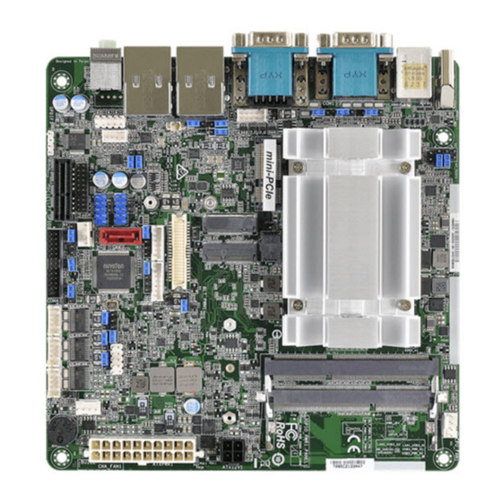
Page 14: Connector Allocation
Case Open Connector COM3 Pin Header PCI-E*1 Connector LVDS Connector SO-DIMM Connector USB 4/5 Connector SATA2 Connector Battery Connector SATA1 Connector ATX Power Connector CF Connector Mini-PCI System FAN (3-pin Smart FAN) JP10 CPU FAN (4-pin Smart FAN) WADE-8070 User’s Manual... - Page 15 TMDS Data 1+ Digital green + TMDS Data 1/3 Shield TMDS Data 3- Digital Blue - TMDS Data 3+ Digital Blue + +5 V Power for monitor when in standby Ground Return for pin 14 and analog sync WADE-8070 User’s Manual...
- Page 16 Signal Description RS-232 RS-422 RS-485 DCD (Data Carrier Detect) DATA- RXD (Receive Data) DATA+ TXD (Transmit Data) DTR (Data Terminal Ready) GND (Ground) DSR (Data Set Ready) RTS (Request to Send) CTS (Clear to Send) RI (Ring Indicator) WADE-8070 User’s Manual...
- Page 17 DCD (Data Carrier Detect) DSR (Data Set Ready) RXD (Receive Data) RTS (Request to Send) TXD (Transmit Data) CTS (Clear to Send) DTR (Data Terminal Ready) RI (Ring Indicator) (Powered +5V/+12V with JP6 selection) GND (Ground ) 10 NC WADE-8070 User’s Manual...
- Page 18 SUS_STAT# J9 : LVDS Inverter Connector PIN No. Signal Description Backlight enable Ground +12V Ground J11 : Front Panel Connector PIN No. Signal Description PIN No. Signal Description 5VSB HD_LED SYS_Reset SUS_LED Ground Ground Power Bottom Speaker WADE-8070 User’s Manual...
- Page 19 DMA ACK# Ground INT REQ HDC CS0# HDC CS1# HDD Active# Ground Ground J13 : GPIO Pin Header PIN No. Signal Description PIN No. Signal Description Ground Ground GPIO0 GPIO5 GPIO1 GPIO6 GPIO2 GPIO7 GPIO3 GPIO8 VCC12 WADE-8070 User’s Manual 2-10...
- Page 20 (Powered +5V/+12V with JP2 selection) GND (Ground ) J19 : LVDS panel signal connector PIN No. Signal Description PIN No. Signal Description LVDSA_DATA0 LVDSA_DATA0# LVDSA_DATA1 LVDSA_DATA1# LVDSA_DATA2 LVDSA_DATA2# LVDSA_CLKP LVDSA_CLKN LVDSB_DATA0 LVDSB_DATA0# LVDSB_DATA1 LVDSB_DATA1# LVDSB_DATA2 LVDSB_DATA2# LVDSB_CLKP LVDSB_CLKN WADE-8070 User’s Manual 2-11...
- Page 21 DATA- DATA- DATA+ DATA+ Ground Ground J26 : ATX power connector PIN No. Signal Description PIN No. Signal Description +3.3V +3.3V Ground Ground Ground PWR_OK +5V stand by +12V +3.3V -12V Ground PS_ON# Ground Ground Ground WADE-8070 User’s Manual 2-12...
- Page 22 Data 13 Data 14 Data 15 SDCS#3 Ground IOR# IOW# Ground RESET# IORDY IDEACT# PDIAG# Data 8 Data 9 Data 10 Ground J29 : Mini-PCI PIN No. Signal Description PIN No. Signal Description INTB# 3.3V INTA# WADE-8070 User’s Manual 2-13...
- Page 23 PERR# DEVSEL# C/BE[1]# Ground AD[14] AD[15] Ground AD[13] AD[12] AD[11] AD[10] Ground Ground AD[09] AD[08] C/BE[0]# AD[07] 3.3V 3.3V AD[06] AD[05] AD[04] AD[02] AD[03] AD[00] AD[01] Ground Ground AC_SYNC M66EN AC_SDATA_IN AC_SDATA_OUT AC_BIT_CLK AC_CODEC_ID0# AC_CODEC_ID1# AC_RESET# WADE-8070 User’s Manual 2-14...
- Page 24 JP8 : System Fan Connector PIN No. Signal Description Ground Fan speed control (voltage control) Fan speed sense JP10 : CPU Fan Connector PIN No. Signal Description Ground +12V Fan Speed Detecting signal Fan Speed Control signal WADE-8070 User’s Manual 2-15...
-
Page 25: Chapter 3 System Installation
Main Memory WADE-8070 provides 1 x 200-pin SO-DIMM sockets which supports 533/400 DDR2-SDRAM as main memory, Non-ECC (Error Checking and Correcting), non-register functions. The maximum memory size can be up to 2GB capacity. -
Page 26: Installing The Single Board Computer
3.3.1 Chipset Component Driver The chipset on WADE-8070 is a new chipset that a few old operating systems might not be able to recognize. To overcome this compatibility issue, for Windows Operating Systems such as Windows 2000 /XP, please install its INF before any of other Drivers are installed. -
Page 27: Realtek Gigabit Ethernet Controller
System Installation Drivers Support Please find Springdale GMCH driver in the WADE-8070 CD-title. Drivers support Windows-2000, Windows XP. 3.3.3 Realtek Gigabit Ethernet Controller Drivers Support Please find Realtek RTL8111C LAN driver in /Ethernet directory of WADE-8070 CD-title. The drivers support Windows 2000 /XP. -
Page 28: Wdt Function
Value of Time-out Value Register : 1) 0x00 -- Time-out Disable 2) 0x01~0xFF -- Value for counting down Value of Sel WDTO RST Register 1) 0x00 -- RST by LPC_RST (Bit3=0) 2) 0x08 -- RST by PWR_OK (Bit3=1) WADE-8070 User’s Manual... -
Page 29: Gpio
System Installation GPIO The WADE-8070 provides 4 input/output ports from SIO that can be individually configured to perform a simple basic I/O function. Users can configure each individual port to become an input or output port by programming register bit of I/O Selection. -
Page 30: Wade-8070 Gpio Programming Guide
System Installation 3.6.1 Wade-8070 GPIO Programming Guide Additionally, 4-extra Digital Output ports inversely amplified signals from GPIO ports. There are open-drain buffers, which can offer greater driving capacity up to 100mA. There are two PNP I/O port addresses that can be used to configure GPIO ports,... - Page 31 If a port is assigned to be an input port, then its respective bit can be read only. Notes: 1) All the Buffered Digital Outputs are open-drain amplified form corresponding GPIO ports. 2) Some other functions may occupy the high nibble of the registers. Altering any content in high nibble will be undesire WADE-8070 User’s Manual...
-
Page 32: Chapter 4 Bios Setup Information
Chapter 4 BIOS Setup Information WADE-8070 is equipped with the AWARD BIOS stored in Flash ROM. These BIOS has a built-in setup program that allows users to modify the basic system configuration easily. This type of information is stored in CMOS RAM so that it is retained during power-off periods. -
Page 33: Main Menu
BIOS Setup Information Main Menu Once you enter WADE-8070 AWARD BIOS CMOS Setup Utility, a Main Menu is presented. The Main Menu allows user to select from eleven setup functions and two exit choices. Use arrow keys to switch among items and press <Enter> key to accept or bring up the sub-menu. -
Page 34: Standard Cmos Setup Menu
Change the day, month, year and century Time hh:mm:ss Change the internal clock IDE Channel 0 Master Options are in its sub Press <Enter> to enter next page for IDE Channel 0 menu detail hard druve settings Slave IDE Channel 1 Master WADE-8070 User’s Manual... -
Page 35: Ide Adaptors Setup Menu
The IDE adapters control the IDE devices, such as hard disk drive or CD-ROM drive. It uses a separate sub menu to configure each hard disk drive. Note: The oblique items are meaning base on what kind of storage device user employs. WADE-8070 User’s Manual... - Page 36 Set the number of cylinders for hard disk Head Min=0, Max=255 Set the number of read/write heads Precomp Min=0, Max=65535 **** Warning: Setting a value of 65535 means no hard disk Landing zone Min=0, Max=65535 **** Sector Min=0, Max=255 Number of sectors per track WADE-8070 User’s Manual...
-
Page 37: Advanced Bios Features
BIOS Setup Information Advanced BIOS Features This section allows you to configure your system for basic operation. You have the opportunity to select the system’s default speed, boot-up sequence, keyboard operation, shadowing and security. WADE-8070 User’s Manual... - Page 38 BIOS Setup Information C1E Function CPU C1E Function Select. The choice: Auto, Disabled. Execute Disabled Bit When disabled, forces the XD feature flag to always return 0. The choice: Enabled, Disabled. Core Multi-Processing The choice: Enabled, Disabled. WADE-8070 User’s Manual...
- Page 39 No warning message will appear when anything attempts to access Disabled the boot sector or hard disk partition table. CPU L1 Cache/L2 Cache These two categories speed up memory access. However, it depends on CPU/chipset design. Enabled Enable Cache Disabled Disable Cache WADE-8070 User’s Manual...
- Page 40 Boot Up NumLock Status Select power on state for NumLock. The choice: Off, On. Gate A20 Option Fast-lets chipsets control GateA20 and Normal – a pin in the keyboard controller controls GateA20. Default is fast. The choice: Normal, Fast. WADE-8070 User’s Manual...
- Page 41 OS Select For DRAM > 64MB Select OS/2 only if you are running OS/2 operating system with greater than 64MB of RAM on the system. The choice: Non-OS2, OS2. Small Logo (EPA) Show The choice: Enabled, Disabled. WADE-8070 User’s Manual 4-10...
-
Page 42: Advanced Chipset Features
This option controls the number of SCLKs between the time a read command is sampled by the DRAMs and the time the GMCH samples correspondent data from the DRAMs. The choice: 3, 4, 5, 6, and Auto. WADE-8070 User’s Manual 4-11... - Page 43 The choice: Enabled, Disabled. Video BIOS Cacheable Select “Enabled” to enable caching VGA BIOS into L2 cache to get higher display performance. “Disabled” to ignore this BIOS caching function. The choice: Enabled, Disabled. WADE-8070 User’s Manual 4-12...
- Page 44 The choice: 64MB, 128MB, 224MB. Boot Display The choice: CRT, LVDS, CRT+LVDS, DVI, CRT+DVI. Panel Scaling The choice: Auto, On, Off. Panel Number The choice: 640x480 18bits, 800x600 18bits, 1024x768 18bits, 1280x1024 24bits. LAN1/LAN2 Control The choice: Enabled, Disabled. WADE-8070 User’s Manual 4-13...
-
Page 45: Integrated Peripherals
BIOS Setup Information Integrated Peripherals WADE-8070 User’s Manual 4-14... - Page 46 Max. of 2 IDE drives in each channel. [Enhanced Mode]: Enable both SATA and PATA. Max. of 4 IDE drives are supported. [SATA only]: Only enable SATA. The Choice: Disabled, Auto, Combined Mode, Enhanced Mode, SATA Only. WADE-8070 User’s Manual 4-15...
- Page 47 Users can enable or disable onboard LAN boot rom Function. The choice: Enabled, Disabled. Onboard Serial Port 3/Port 4 Select an address and corresponding interrupt for the first and second serial ports. The choice: Disabled, 3F8/IRQ4, 2F8/IRQ3, 3E8/IRQ4, 2E8/IRQ3, Auto. WADE-8070 User’s Manual 4-16...
- Page 48 USB 1.0 Controller [Enabled] or [Disabled] Universal host controller interface for universal serial bus. The choice: Enabled, Disabled. USB 2.0 Controller [Enabled] or [Disabled] Enhanced host controller interface for universal serial bus. The choice: Enabled, Disabled. WADE-8070 User’s Manual 4-17...
- Page 49 Full/Low speed mode. The choice: High Speed, Full/Low Speed. USB Keyboard/Mouse Function [Enabled] or [Disabled] Legacy support of USB keyboard or mouse. The choice: Disabled, Enabled. USB Storage Function [Enabled] or [Disabled] Legacy support of USB Mass Storage. WADE-8070 User’s Manual 4-18...
-
Page 50: Power Management Setup
This item allows you to enable/disable the Advanced Configuration and Power Management (ACPI). The choice: Enabled, Disabled. ACPI Suspend Type To decide which ACPI suspend mode to use. The choice: S1 (POS), S3 (STR). Run VGA BIOS if S3 Resume The choice: Auto, Yes, No. WADE-8070 User’s Manual 4-19... - Page 51 When enabled and after the set time of system inactivity, all devices except the CPU will be shut off. The choice: Disabled, 1 Min, 2 Min, 4 Min, 8 Min, 12 Min, 20 Min, 30 Min, 40 Min, and 1 Hour. WADE-8070 User’s Manual 4-20...
- Page 52 The choice: Enabled, Disabled. ※Date(of Month) Alarm When “Resume by Alarm” is enabled, this item could allow users to configure the date parameter of the timing dateline on which to power on the system. The choice: 0 ~ 31. WADE-8070 User’s Manual 4-21...
- Page 53 The choice: Enabled, Disabled. PCI PIRQ[A-D]# This option can be used to detect PCI device activities. If they are activities, the system will go into sleep mode. The choice: Enabled, Disabled. WADE-8070 User’s Manual 4-22...
-
Page 54: Pnp/Pci Configurations
Default is Disabled. Select Enabled to reset Extended System Configuration Data (ESCD) when you exit Setup if you have installed a new add-on and the system reconfiguration has caused such a serious conflict that the OS cannot boot. The choice: Enabled, Disabled. WADE-8070 User’s Manual 4-23... - Page 55 Legacy ISA for devices compliant with the original PC AT bus specification, PCI PnP for devices compliant with the plug and play standard whether designed for PCI bus architecture. The choice: Enabled, Disabled. Maximum Payload Size. Default 128. The choice: 128, 256, 542, 1024, 2048, 4096. WADE-8070 User’s Manual 4-24...
-
Page 56: Pc Health Status
This item allows you to set a temperature above which the system will start the beeping warning. Default setting is disabled. This function will only with “ACPI” power management and “S3 (STR)” suspends type. The choices: Disabled, 50℃/122℉, 53℃/127℉, 56℃/133℉, 60℃/140℉, 63℃/145 ℉, 66℃/151℉, 70℃/158℉. WADE-8070 User’s Manual 4-25... -
Page 57: Default Menu
To disable a password, just press <Enter> when prompted to enter the password. A message will confirm the password will be disabled. Once the password is disabled, the system will reboot and Setup can be entered freely. WADE-8070 User’s Manual 4-26... -
Page 58: Exiting Selection
Pressing <Enter> on this item asks for confirmation: Quit Without Saving (Y/N)? N This allows user to exit Setup without storing in CMOS any change. The previous selections remain in effect. This exits the Setup utility and restarts your computer. WADE-8070 User’s Manual 4-27... -
Page 59: Chapter 5 Troubleshooting
Chapter 5 Troubleshooting This chapter provides a few useful tips to quickly get WADE-8070 running with success. As basic hardware installation has been addressed in Chapter 2, this chapter will primarily focus on system integration issues, in terms of BIOS setting, and OS diagnostics. -
Page 60: Bios Setting
BIOS setting back to the initial factory configuration. It is recommended to do this so you can be sure the system is running with the BIOS setting that Portwell has highly endorsed. As a matter of fact, users can load the default BIOS setting any time when system appears to be unstable in boot up sequence. - Page 61 IRQ #15 Usable IRQ It is then very easy to find out which IRQ resource is ready for additional peripherals. If IRQ resource is not enough, please disable some devices listed above to release further IRQ numbers. WADE-8070 User’s Manual...
-
Page 62: Ordering Setting
Please visit our technical web site at http://www.portwell.com.tw For additional technical information, which is not covered in this manual, you can mail to tsd@mail.portwell.com.tw or you can also send mail to our sales, they wull be very delighted to forward them to us. WADE-8070 User’s Manual... - Page 63 Program Area 0F6C-9EFF 574K [Available] = Conventional memory ends at 636K = 9F00-9FBF Extended BIOS Area 9FC0-9FFF Unused A000-AFFF VGA Graphics B000-B7FF Unused B800-BFFF VGA Text C000-CEBF Video ROM CEC0-EFFF 133K Unused F000-FFFF System ROM First 64K Extended WADE-8070 User’s Manual...
- Page 64 Usable IRQ IRQ 10 [Unassigned] Usable IRQ IRQ 11 [Unassigned] Usable IRQ IRQ 12 System ROM IBM Mouse Event IRQ 13 System ROM Coprocessor Error IRQ 14 System ROM Hard Disk Event IRQ 15 [Unassigned] Usable IRQ WADE-8070 User’s Manual...
Need help?
Do you have a question about the WADE-8070 and is the answer not in the manual?
Questions and answers