
Subscribe to Our Youtube Channel
Related Manuals for Portwell WADE-8171


Summary of Contents for Portwell WADE-8171
- Page 1 WADE-8171 WADE‐8171 Industrial Mini‐ITX Board Version 0.1 Copyright © Portwell 2015 WADE-8171 User's Guide...
- Page 2 WADE-8171 Revision History R0.1 Preliminary Copyright © Portwell 2015 WADE-8171 User's Guide...
-
Page 3: Table Of Contents
Signal Descriptions ....................................... 42 Watch Dog Signal ....................................42 GPIO Signal ......................................42 System Resources ........................................ 44 BIOS Setup Items ......................................... 46 Introduction ......................................46 BIOS Setup ......................................46 7.2.1 Main ........................................... 48 7.2.2 Configuration......................................... 50 Copyright © Portwell 2015 WADE-8171 User's Guide... - Page 4 WADE-8171 7.2.3 Security ........................................74 7.2.4 Boot 7.2.5 Exit ........................................... 82 Troubleshooting ........................................84 Hardware Quick Installation ................................... 84 BIOS Setting......................................86 FAQ ........................................87 Portwell Software Service ...................................... 92 Industry Specifications......................................93 Copyright © Portwell 2015 WADE-8171 User's Guide...
- Page 5 Portwell provides no warranty with regard to this user’s guide or any other information contained herein and hereby expressly disclaims any implied warranties of merchantability or fitness for any particular purpose with regard to any of the foregoing. Portwell assumes no liability for any damages incurred directly or indirectly from any technical or typographical errors or omissions contained herein or for discrepancies between the product and the user’s guide.
- Page 6 Warranty”). Portwell may in its sole discretion modify its Limited Warranty at any time and from time to time. Beginning on the date of shipment to its direct customer and continuing for the published warranty period, Portwell represents that the products are new and warrants that each product failing to function properly under normal use, due to a defect in materials or workmanship or due to non conformance to the agreed upon specifications, will be repaired or exchanged, at Portwell’s option and expense.
-
Page 7: Introduction
WADE-8171 1 Introduction WADE-8171 based on the Intel® Core™ Processor which offers 14nm Hi-K process technology with energy efficient architecture. WADE-8171 support dual channels DDR3LSO- DIMM up to 8GB. Desktop solution is still popular in the market of DVR and Factory Automation which can fulfill most of these applications; therefore, with high performance and high-end specifications, Braswell SoC is our first generation Atom chip architecture on Mini-ITX line. -
Page 8: Specifications
◆ GPIO connector: 8GPI + 8GPO ◆ Audio Interface: Connector for Mic-In and Line-Out ◆ Supports dual 10/100/1000 Mbps Ethernet port (s) via PCI Express x1 bus which provides 500 MB/s Ethernet data transmission rate Copyright © Portwell 2015 WADE-8171 User's Guide... -
Page 9: Supported Operating Systems
◆ Power supply voltage: +3.3 V, +5 V, +12 V, 5 Vsb ◆ Board size: 170mm x 170 mm Supported Operating Systems The WADE-8171 supports the following operating systems. Windows* 8.1u (64 bit) * Windows* Embedded Industry 8.1 (64 bit) ... -
Page 10: Mechanical Dimensions
WADE-8171 Mechanical Dimensions Copyright © Portwell 2015 WADE-8171 User's Guide... -
Page 11: Power Consumption
Realtek ALC887 High Definition Audio Version 6.0.1.7464 Chipset Driver Intel® Braswell Chipset Device Software Version: 10.0.13 SATA HDD HITACHI H2T250854SEA7N250GB SATA DOM ASUS DRW-24B3ST ATA Device USB DVDROM PIONEER DVD-RW DVR-XD11 Power Supply FSB GROUP FSP460-60PFB 460W Copyright © Portwell 2015 WADE-8171 User's Guide... -
Page 12: Environmental Specifications
USB3.0 Loading Test 5.01 V/ 1090mA DCIN Item +12V 0.09 0.12 0.12 0.08 +5VSB 0.08 0.11 0,10 0.09 Environmental Specifications Storage Temperature : -20~80°C Operation Temperature : 0~60°C Storage Humidity : 5~90% Operation Humidity: 10~90% Copyright © Portwell 2015 WADE-8171 User's Guide... -
Page 13: Block Diagram
WADE-8171 3 Block Diagram Copyright © Portwell 2015 WADE-8171 User's Guide... -
Page 14: Hardware Configuration
WADE-8171 4 Hardware Configuration Jumpers and Connector This chapter indicates jumpers’, headers’ and connectors’ locations. Users may find useful information related to hardware settings in this chapter. Copyright © Portwell 2015 WADE-8171 User's Guide... -
Page 15: Jumpers Setting
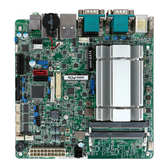
Jumpers Setting For users to customize WADE-8171’s features. In the following sections, Short means covering a jumper cap over jumperpins; Open or N/C (Not Connected) means removing a jumper cap from jumper pins. Users can refer to Figure 1 for the Jumper allocations. - Page 16 USB2 Power Setting Jumper(for USB2_0_1) Clear CMOS Header USB2.0 Connector(USB2_0_1) 3W Audio AMP Output Wafer Front Panel Audio Header Audio Output Backlight Power Select(LCD_BLT_VCC)(BKT_PWR1) Top:RJ45 LAN port(LAN2) Backlight Power Connector(BLT_PWR1) Top:RJ45 LAN port(LAN1) LAN LED Copyright © Portwell 2015 WADE-8171 User's Guide...
- Page 17 WADE-8171 VGA Header TOP:COM Port 3 (RS232/422/485) Bottom: VGA/D-Sub Port mSATA Select Top: COM Port 1(RS232/422/485)* Bottom: COM Port 2(RS232/422/485)* PS/2 Mouse/Keyboard Port HDMI Port Copyright © Portwell 2015 WADE-8171 User's Guide...
- Page 18 WADE-8171 Copyright © Portwell 2015 WADE-8171 User's Guide...
- Page 19 WADE-8171 Copyright © Portwell 2015 WADE-8171 User's Guide...
- Page 20 WADE-8171 Copyright © Portwell 2015 WADE-8171 User's Guide...
- Page 21 WADE-8171 Copyright © Portwell 2015 WADE-8171 User's Guide...
- Page 22 WADE-8171 Copyright © Portwell 2015 WADE-8171 User's Guide...
- Page 23 WADE-8171 Copyright © Portwell 2015 WADE-8171 User's Guide...
- Page 24 WADE-8171 Copyright © Portwell 2015 WADE-8171 User's Guide...
- Page 25 WADE-8171 Copyright © Portwell 2015 WADE-8171 User's Guide...
- Page 26 WADE-8171 Copyright © Portwell 2015 WADE-8171 User's Guide...
- Page 27 WADE-8171 Copyright © Portwell 2015 WADE-8171 User's Guide...
- Page 28 WADE-8171 Copyright © Portwell 2015 WADE-8171 User's Guide...
- Page 29 WADE-8171 Copyright © Portwell 2015 WADE-8171 User's Guide...
- Page 30 WADE-8171 Copyright © Portwell 2015 WADE-8171 User's Guide...
- Page 31 WADE-8171 Copyright © Portwell 2015 WADE-8171 User's Guide...
-
Page 32: Connector Settings
USB 3.0/100M/1G Lan Connector (LAN2) LAN RJ45+USB3.0x2 WGI210AT Front Panel System Connector HEADER 8PX2 ATX 4Pin 12V Power Connector MA 2Px2. ATX4PT-L.TechBest SMBus Connector PH5Px1-Pin2/2.54mm PS/2 Keyboard/Mouse Connector HEADER5X2/nc3,4 GPIO Header5Px2/2.54mm J12/J13/J14/J15 COM3~COM10 Serial Port Connector BH5Px2/2.54mm Copyright © Portwell 2015 WADE-8171 User's Guide... - Page 33 FAN_Header4Px1 J21/J26/J27/J28 DDR3 Long DIMM Connector DDR3-Slot/240Pin J25/J24/J23/J22 External USB Connector HEADER 5PX2(-9) J29/J30/J33/J34/ SATA Connector(6Gb/s) SATA/Blue TPM(Trusted Platform Module) Connector BH10Px2/2.0mm CFEX Slot CFEX ATX Power ATX24/180D SYSTEM FAN Power Connector Connector3Px1/2.54mm Copyright © Portwell 2015 WADE-8171 User's Guide...
- Page 34 PIN No. Signal Description PIN No. Signal Description PWR_LED(+) PWR_LED(-) LAN1_ACT(+) LAN1_LINK(-) BUZZER LAN2_LINK(-) LAN2_ACT(+) Power Button HDD_LED(+) Rest HDD_LED(-) J7: ATX 4Pin 12V Power Connector PIN No. Signal Description Ground Ground +12V +12V Copyright © Portwell 2015 WADE-8171 User's Guide...
- Page 35 PIN No. Signal Description SMBus_CLK Ground SMBus_DAT J9: PS/2 Keyboard/Mouse Connector PIN No. Signal Description PIN No. Signal Description Mouse Data Keyboard Data Ground Ground PS2 Power PS2 Power Mouse Clock Keyboard Clock Copyright © Portwell 2015 WADE-8171 User's Guide...
- Page 36 Signal Description DCD (Data Carrier Detect) 2 DSR (Data Set Ready) RXD (Receive Data) RTS (Request to Send) TXD (Transmit Data) CTS (Clear to Send) DTR (Data Terminal RI (Ring Indicator) Ready) GND (Ground) Copyright © Portwell 2015 WADE-8171 User's Guide...
- Page 37 PIN No. Signal Description Ground +12V Fan on/off output Fan Speed control J25/J24/J23/J22: External USB Connector PIN No. Signal Description PIN No. Signal Description 5V Dual 5V Dual USB- USB- USB+ USB+ Ground Ground Copyright © Portwell 2015 WADE-8171 User's Guide...
- Page 38 WADE-8171 J29/J30/J33/J34/J37: SATA Connector(6Gb/s) PIN No. Signal Description GND1 GND2 GND3 Copyright © Portwell 2015 WADE-8171 User's Guide...
- Page 39 WADE-8171 J31 TPM(Trusted Platform Module) Connector PIN No. Signal Description PIN No. Signal Description PCLK_TPM Ground LFRAME# PLT_RST_N LAD2 LAD3 LAD1 VCC3 Ground LAD0 SMB_DATA_MAIN SMB_CLK_MAIN SERIRQ 3VSB LPCPD# LDRQ#1 Ground Ground Copyright © Portwell 2015 WADE-8171 User's Guide...
- Page 40 WADE-8171 J32 CFEX Slot PIN No. Signal Description PIN No. Signal Description PIN No. Signal Description SPI_CLK SPI_MISO RX1- RX1+ SPI_MOSI WP0# TX0+ TX0- SPI_CS# WP1# RX0- RX0+ TX1+ SPI_WP# TX1- Copyright © Portwell 2015 WADE-8171 User's Guide...
- Page 41 +3.3V +3.3V -12V Ground Ground PS_ON# Ground Ground Ground Ground Ground ATX_PWROK +5VSB +12V1 +12V1 +3.3V Ground J36: SYSTEM FAN Power Connector PIN No. Signal Description Ground Fan speed control Fan on/off output Copyright © Portwell 2015 WADE-8171 User's Guide...
-
Page 42: Signal Descriptions
O 2E F1 O 2F (XX) (XX):Watchdog Timer Counter Register(0x00~0xFF) O 2E AA GPIO Signal GPI program sample O 2E 87 O 2E 87 O 2E 07 O 2F 07 Select Logical Device 7 Copyright © Portwell 2015 WADE-8171 User's Guide... - Page 43 GP4x pins are programmed as output pins O 2F 00 GP4x pins are programmed as output pins O 2E F1 GPIO status 1:high, 0: low O 2F yy xx = GPIO status 1:high, 0: low O 2E AA Copyright © Portwell 2015 WADE-8171 User's Guide...
-
Page 44: System Resources
Available 0FC3-9AFF 556K 9B00-9CFF Unused First Meg -- Conventional memory end at 628K -- 9D00-9DFF Extended BIOS Area 9G00-9FFF Unused A000-AFFF VGA Graphics B000-B7FF Unused B800-BFFF VGA Text C000-CE9F Video ROM CEA0-D09F Unused Copyright © Portwell 2015 WADE-8171 User's Guide... - Page 45 IRQ 10 Usable IRQ IRQ 11 Unassigned Usable IRQ IRQ 12 System ROM IBM Mouse Event IRQ 13 System ROM Coprocessor Error IRQ 14 System ROM Hard Disk Event Unassigned IRQ 15 Usable IRQ Copyright © Portwell 2015 WADE-8171 User's Guide...
-
Page 46: Bios Setup Items
The BIOS setup program provides a GeneralHelp screen. The menu can be easily called up from any menu by pressing <F1>. The Help screen lists all the possible keys to use and the selections for the highlighted item. Press <Esc> to exit the Help Screen. Copyright © Portwell 2015 WADE-8171 User's Guide... - Page 47 WADE-8171 Copyright © Portwell 2015 WADE-8171 User's Guide...
-
Page 48: Main
To set up the system time/date information. Feature Description Options System Date Set the Date. Use Tab to switch between Date elements. System Time Set the Time. Use Tab to switch between Time elements Copyright © Portwell 2015 WADE-8171 User's Guide... - Page 49 WADE-8171 Advancd To set up the advanced UEFI features. Copyright © Portwell 2015 WADE-8171 User's Guide...
-
Page 50: Configuration
WADE-8171 7.2.2 Configuration CPU Configuration CPU Configuration Parameters. Copyright © Portwell 2015 WADE-8171 User's Guide... - Page 51 Intel Virtualization Technology allows a platform to run multiple operating systems Intel Virtualization Technology and applications in independent partitions, so that one computer system can Disabled, Enabled ★ function as multiple virtual systems. Copyright © Portwell 2015 WADE-8171 User's Guide...
- Page 52 WADE-8171 Chipset Configuration Configure Chipset Settings. Copyright © Portwell 2015 WADE-8171 User's Guide...
- Page 53 Active LVDS The enable or disable the LVDS. ★ Enabled, Disabled 1366x768/18-bit/1-ch/LED,800x600/ 18-bit/1-ch/CCFL, 1024x768/24-bit/1-ch/CCFL, 1280x1024/24-bit/2-ch/CCFL, 1366x768/24-bit/1-ch/CCFL, ★ 1440x900/24-bit/2-ch/LED, 1024x600/18-bit/1-ch/LED, Panel Type Selection Select Panel Type 1440x900/24-bit/2-ch/LED, 1280x1024/24-bit/2-ch/LED, 1024x768/24-bit/1-ch/LED, 1600x900/18-bit/2-ch/LED,1366x768 /24-bit/1-ch/LED, 1920x1080/24-bit/2-ch/LED, 800x600/24-bit/1-ch/LED, 640x480/24-bit/1-ch/LED, Copyright © Portwell 2015 WADE-8171 User's Guide...
- Page 54 Configure PCIE1 Slot Link Speed. ★ Auto, Gen2, Gen1 Select system deep S5 configuration. Deep S5 ‘Auto’ will disable the deep S5 configuration if RTC/LAN/USB device ★ Auto, Disabled power on settings enabled. Copyright © Portwell 2015 WADE-8171 User's Guide...
- Page 55 WADE-8171 Storage Configuration Configure storage devices. Copyright © Portwell 2015 WADE-8171 User's Guide...
- Page 56 Hard Disk S.M.A.R.T stands for Self-Monitoring, Analysis, and Reporting Technology. It is a monitoring system Disabled, Enabled ★ S.M.A.R.T for computer hard disk drivers to detect and report on various indicators of reliability. Copyright © Portwell 2015 WADE-8171 User's Guide...
- Page 57 WADE-8171 SATA3_1: Hitachi HCT721010SLA360 Feature Description Options Hot Plug Designates this port as Hot Pluggable. Enabled, Disabled ★ Copyright © Portwell 2015 WADE-8171 User's Guide...
- Page 58 WADE-8171 SATA3_2/MINI_SATA1: WDC WD5002ABYS-01B1B0 Feature Description Options Hot Plug Designates this port as Hot Pluggable. abled, Disabled ★ Copyright © Portwell 2015 WADE-8171 User's Guide...
- Page 59 Configure Super IO Settings. Feature Description Options WDT Timeout Reset Enable/Disable Watch Dog Timer timeout to reset system. ★ Disabled, Enabled WDT Initial Value (Sec.) Watch Dog Timer Initial Value to count down. Range: 1-255 Copyright © Portwell 2015 WADE-8171 User's Guide...
- Page 60 WADE-8171 COM1 Configuration Set Parameter of COM1 Feature Description Options Serial Port Enable or Disable Serial Port(COM) Disabled, Enabled ★ Type Select Set COM Type. ★ RS-232, RS422, RS485 Copyright © Portwell 2015 WADE-8171 User's Guide...
- Page 61 WADE-8171 COM2 Configuration Set Parameter of COM2 Feature Description Options Serial Port Enable or Disable Serial Port(COM) Disabled, Enabled ★ Type Select Set COM Type. ★ RS-232, RS422, RS485 Copyright © Portwell 2015 WADE-8171 User's Guide...
- Page 62 WADE-8171 COM3 Configuration Set Parameter of COM3 Feature Description Options Serial Port Enable or Disable Serial Port(COM) Disabled, Enabled ★ Type Select Set COM Type. ★ RS-232, RS422, RS485 Copyright © Portwell 2015 WADE-8171 User's Guide...
- Page 63 WADE-8171 COM4 Configuration Set Parameter of COM4 Feature Description Options Serial Port Enable or Disable Serial Port(COM) Disabled, Enabled ★ Copyright © Portwell 2015 WADE-8171 User's Guide...
- Page 64 WADE-8171 COM5 Configuration Set Parameter of COM5 Feature Description Options Disabled,★Enabled Serial Port Enable or Disable Serial Port(COM) Copyright © Portwell 2015 WADE-8171 User's Guide...
- Page 65 WADE-8171 COM6 Configuration Set Parameter of COM6 Feature Description Options Serial Port Enable or Disable Serial Port(COM) Disabled, Enabled ★ Copyright © Portwell 2015 WADE-8171 User's Guide...
- Page 66 WADE-8171 LPT1 Port Configuration Set Parameter of COM1 Copyright © Portwell 2015 WADE-8171 User's Guide...
- Page 67 Change the Printer mode. ★ ECP and EPP 1.9 Mode, ECP and EPP 1.7 Mode ★ Auto IO=378h; IRQ=5, DMA=3 Change Settings Select an optimal settings for Super IO Device IO=378h; IRQ=5,6,7,9,10,11,12; DMA=1,3 IO=278h; IRQ=5,6,7,9,10,11,12; DMA=1,3 Copyright © Portwell 2015 WADE-8171 User's Guide...
- Page 68 WADE-8171 ACPI Configuration Configure ACPI Settings Copyright © Portwell 2015 WADE-8171 User's Guide...
- Page 69 USB Keyboard/Remote Power On Enable system to wake up from S5 using USB Keyboard/Remote. ★ Disabled, Enabled USB Mouse Power On Enable system to wake up from S5 using USB Mouse ★ Disabled, Enabled Copyright © Portwell 2015 WADE-8171 User's Guide...
- Page 70 Enables Legacy USB support. Legacy USB Auto option disables legacy support if no USB devices are connected. DISABLE option will ★ Enabled, Disabled, Auto Support keep USB devices available only for EFI applications. Copyright © Portwell 2015 WADE-8171 User's Guide...
- Page 71 Save UEFI files in your USB storage device and run Instant Flash to update your UEFI. Please note that your USB storage device must be FAT32/16/12 file system. H/W Monitor To display current hardware status Copyright © Portwell 2015 WADE-8171 User's Guide...
- Page 72 Level9 ★ CHA_FAN1 Setting Quiet Fan Function Control ★ Full On, Automatic mode (Automatic mode) Target CPU Temperature Target CPU Temperature Value. 45 / 113 , 46 /114 , ℃ ℉ ℃ ℉ Copyright © Portwell 2015 WADE-8171 User's Guide...
- Page 73 The higher the level, the higher the fan speed. Level 4, Level 5, Level 6 Level 7, Level 8, Level9 ★ Case Open Feature Enable or disable the feature of Case Open. ★ Disabled, Enabled Copyright © Portwell 2015 WADE-8171 User's Guide...
-
Page 74: Security
WADE-8171 7.2.3 Security To setup the security features. Copyright © Portwell 2015 WADE-8171 User's Guide... - Page 75 Set or change the password for the user account. Users are unable to change the settings in User Password the UEFI Setup Utility. Create New password Leave it blank and press enter to remove the password. Secure Boot Enable to support Windows 8 Secure Boot. ★ Disabled, Enabled Copyright © Portwell 2015 WADE-8171 User's Guide...
-
Page 76: Boot
WADE-8171 7.2.4 Boot To setup the default system device to locate and load the Operating System. Copyright © Portwell 2015 WADE-8171 User's Guide... - Page 77 Full Screen Logo Enable to display the boot logo or disable to show normal POST messages. Disabled, Enabled ★ AddOn ROM Set display mode for Option Rom ★Enabled, Disabled Display Copyright © Portwell 2015 WADE-8171 User's Guide...
- Page 78 WADE-8171 Hard Drive BBS Priorities Set the order of the legacy devices in this group Copyright © Portwell 2015 WADE-8171 User's Guide...
- Page 79 Options ★ SATA3_1: Hitachi HCT721010SLA360, SATA3_2/MINI_SATA: WDC Boot Option #1 Sets the system boot order WD5002ABYS-01B10, Disabled SATA3_1: Hitachi HCT721010SLA360, ★ SATA3_2/MINI_SATA: WDC Boot Option #2 Sets the system boot order WD5002ABYS-01B10, Disabled Copyright © Portwell 2015 WADE-8171 User's Guide...
- Page 80 WADE-8171 CSM(Compatibility Support Module) OpROM execution, boot options filter, etc. Copyright © Portwell 2015 WADE-8171 User's Guide...
- Page 81 Do not launch, Launch Video OpROM policy to run those that support legacy option ROM only. Select Do not launch to not execute UEFI only, both legacy and UEFI option ROM. ★ Legacy only Copyright © Portwell 2015 WADE-8171 User's Guide...
-
Page 82: Exit
WADE-8171 7.2.5 Exit To exit the current screen or the UEFI SETUP UTILITY' Copyright © Portwell 2015 WADE-8171 User's Guide... - Page 83 Load UEFI Default values for all the setup questions. Load UEFI Defaults F9 key can be used for this operation. Attempts to Launch FEI Shell application (Shell.efi) from one of the Launch EFI Shell from filesystem device available filesystem devices Copyright © Portwell 2015 WADE-8171 User's Guide...
-
Page 84: Troubleshooting
WADE-8171 8 Troubleshooting This section provides a few useful tips to quickly get WADE-8171 running with success. This section will primarily focus on system integration issues, in terms of BIOS setting, and OS diagnostics. Hardware Quick Installation ATX Power Setting Unlike other Single board computer, WADE-8171 supports AT/ATX only. - Page 85 Unlike IDE bus, each Serial ATA channel can only connect to one SATA hard disk at a time; The installation of Serial ATA is simpler and easier than IDE, because SATA hard disk doesn’t require setting up Master and Slave, which can reduce mistake of hardware installation. Copyright © Portwell 2015 WADE-8171 User's Guide...
-
Page 86: Bios Setting
To make sure that you have a successful start with WADE-8171, it is recommended, when going with the boot-up sequence, to hit “F2 ” or ” Del” key and enter the BIOS setup menu to tune up a stable BIOS configuration so that you can wake up your system far well. -
Page 87: Faq
This will force your BIOS setting back to the initial factory configurations. It is recommended to do this so you can be sure the system is running with the BIOS setting that Portwell has highly endorsed. As a matter of fact, users can load the default BIOS setting at any time when system appears to be unstable in boot up sequence. - Page 88 WADE-8171 Question: How to update the BIOS file of WADE-8171? Answer: 1. Please visit web site of Portwell download center as below hyperlink http://www.portwell.com.tw/support/download_center.php Registering an account in advance is a must. (The E-Mail box should be an existing Company email address that you check regularly.) http://www.portwell.com.tw/member/newmember.php...
- Page 89 WADE-8171 6. When you see the “FPT Operation Passed” message, which means the BIOS update processes finished. Please cut the AC power off and wait for 10 seconds before powering on. Copyright © Portwell 2015 WADE-8171 User's Guide...
- Page 90 BIOS update processes. Question: What are the display options while using WADE-8171 with PCOM-C600 carrier board? Answer: The PCOM-C600 carrier board does not support DVI display output with WADE-8171. It supports the VGA (Using DVI to VGA adapter) and LVDS output.
- Page 91 If you have other additional technical information or request which is not covered in this manual, please fill in the technical request form as below hyperlink. http://www.portwell.com.tw/support/problem_report.php We will do our best to provide a suggestion or solution for you. Thanks Copyright © Portwell 2015 WADE-8171 User's Guide...
-
Page 92: Portwell Software Service
Portwell. Portwell BIOS web Tool (PBT) The Portwell BIOS web Tool (PBT) is a brand new on-line utility which innovated by Portwell. PBT now is available for Portwell's premiere customers who are able to add customized BIOS logo change BIOS default settings on American Megatrends (AMI) BIOS. -
Page 93: Industry Specifications
WADE-8171 10 Industry Specifications The list below provides links to industry specifications that apply to Portwell modules. Low Pin Count Interface Specification, Revision 1.0 (LPC)http://www.intel.com/design/chipsets/industry/lpc.htm Universal Serial Bus (USB) Specification, Revision 2.0http://www.usb.org/home PCI Specification, Revision 2.3 https://www.pcisig.com/specifications Serial ATA Specification, Revision 3.0 http://www.serialata.org/...
Need help?
Do you have a question about the WADE-8171 and is the answer not in the manual?
Questions and answers