Table of Contents
Advertisement
Advertisement
Table of Contents

Related Manuals for First Degree Fitness Fluid E920


Summary of Contents for First Degree Fitness Fluid E920
-
Page 1: Owners Manual
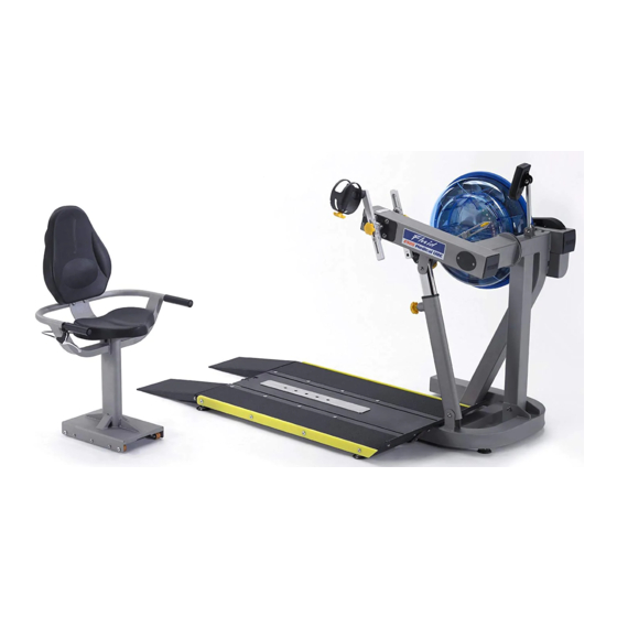
Owners Manual Wheelchair Accessible... -
Page 2: Table Of Contents
Contents 1. Contents of E920 Box. 2. E920 Assembly Instructions. 3. E920 Control Arm. 4. E920 Slider Arm Kit. 5. Tank Filling and Water Treat- ment. 6. Long Term Water Treatment CAUTION and Basic Operation. As with any piece of fitness equipment, 7. - Page 3 Box Contents E920 1x Main Frame with Telescoping Tube and Internal Gas Assist Shock 1x Seat and Base 1x Fill Funnel and Hose 2x Mainframe Bolts 3x Frame levelers 4x Spring Washers M10x 25 Hex Key 4x Frame Bolt M3x130x25 Washers 4x Telescoping 1x M6...
-
Page 4: E920 Assembly Instructions
E920 Assembly Instructions 4x 8x15mm Bolts and 4x M8 Spring Washers 3x Foot Leveler Adjuster Knob Step 1: Remove contents from box. Attach telescoping tube to the underside of the control arm using 4x M8x15mm bolts and 4x M8 spring washers. CAUTION The control arm is heavy and will swing freely during this stage of assembly. - Page 5 E 920 Baseplate Addendum: CONTENTS: PVC Sidecovers Ramp Right T-Track Ramp left Note hardware bolt pack is used E 920 Mainframe for both Seat Assembly and Baseplate. Step 1: Bolt the T- Track to the Main- Remove contents from box and frame as shown, us- make sure all parts are present.
- Page 6 Step 2: Attach Left and Right ramps to the T-track using 8x M8x45mm bolts M8x45mm bolts 4x M8x25 bolt, 4x M8 Ny- lock nut and 4x M8 washer. Step 3: Once the Left and Right ramps have been installed to the sides of the T-track, se- cure the front end of each ramp as shown using 4x M8x25 bolt, 4x M8 Nylock nut and 4x M8 washer.
- Page 7 Install Seat onto Baseplate Seat Stop: Must be lowered to al- low seat onto Baseplate track. Must ALWAYS be in the LOCKED position when seat is occupied on Baseplate. Must be lowered to allow seat re- moval. To LOCK, raise and locate. To UNLOCK, lift and drop rearward.
- Page 8 Seat Assembly: Seat Main Frame Armrest Assembly Upper Seat back Bolt Pack Seat CONTENTS: 1x Seat Main Frame 1x Lower Seat 1x Armrest Assembly 1x Upper Seat back 1x Bolt Pack (Note Bolts/Washers/Nuts are for both Seat and Footplate)
- Page 9 Attaching Armrest to Lower frame You will need the Lower Frame, Armrest Assembly and the following bolts/ washers/nuts from the bolt Pack: 1x M8x70mm Bolt 3x M8 Nylock Nut 1x M8x25mm Bolt 1x M8 Washer 2x M8x45mm Bolt Plastic tie Step One: Mount the Armrest onto the Lower frame from behind as shown.
- Page 10 Attaching Armrest to Lower frame: Step One: Secure Armrest with M8x70mm Bolt, M8 Nylock Nut and M8 Washer as shown Step Two: M8x25mm Bolt Step Three: 2x M8x45mm Bolt,2x Nylock Nut and and M8 Washer 2x M8 Washer...
- Page 11 Attaching Armrest cable to Cable Pivot: Cable Pivot Cable Pivot Step One: Locate plastic tie, then depress Cable Pivot forward to allow plastic tie to be pulled through the hole in front. Once the cable end is through the hole, slide it forward as shown upper right to prevent cable end from slipping back through.
- Page 12 Seat Assembly Attaching Upper/Lower Seat Pad: Seat Frame, Upper/Lower Seat Pad, 8x M6x20mm Bolt and 8x M8 Washer Install Lower Seat Pad Using 4x M6x20mm Bolt/Washer Install Upper Seat Pad with as shown with 4x M6x20mm Bolt/Washer. Once seat pads are installed the assembly will be complete.
-
Page 13: E920 Control Arm
The E920 Control Arm Chain tensioning bolts: Allows for tightening the chain or adjustment from side to side. Make sure when tightening only to adjust the same amount for both bolts, otherwise the sprocket will be misaligned. Note: Tightening the right bolt only (turning clockwise) will pull the right side of the crank assembly toward you, tightening the left will pull the left side toward you. -
Page 14: E920 Slider Arm Kit
E920 Slider Arm Kit Installation Instructions Slider Arm Kit includes 1x Slider Arm Assembly Right (includes right handle), 1x Slider Arm Assembly Left (includes left handle), 2x Yellow Adjustment Knobs with Nylon Spac- ers and 1x 3mm Allen key. Note: Slider Arms are marked ‘L’ and ‘R’. - Page 15 E920 Slider Arm Kit Installation Instructions Step 3: Thread Adjustment Knob onto axle to secure the assembly. Step 1: Mount the left Slider Arm onto the axle using the yellow indicator hole to align the slider and axle. Step 2: Tighten the set screw onto the axle and into the yellow indicator hole using the 3mm Allen key.
- Page 16 Using the E920 Slider Arm The E920 Slider Arm Kit offers the user an entire range of added resistance settings and the ability to perform additional upper body workouts. To adjust, simply loosen the Adjustment Knobs, move Slider Arm to desired length and secure. Very little tension is needed. What do the numbers mean? The numbers represent the length (in cm) from the center of the axle to the center of the handgrip shaft bolt.
-
Page 17: Tank Filling And Water Treatment
Tank Filling and Water Treatment Note: A large bucket is required for filling (Not included). In areas where tap water quality is known to be poor, FDF recommends the use of distilled water. Open the tank plug and insert hose into tank (rotating the im- peller slightly may be neces- sary to allow the hose to pass), move the tank adjuster... -
Page 18: Long Term Water Treatment And Basic Operation
Long term water treatment: Do not use any water treatment other than the tablets supplied with this ma- chine. For replacement tablets, contact your local First Degree Fitness distributor or visit www.firstdegreefitness.com for distributor locations. Water treatment schedules for the E920 will vary according to the fluid tanks expo- sure to sunlight but expect 8-12 months near a bright, sunlit window and 2-4 years for a darker location. - Page 19 E920 Ergometer. Note: For complete operational Quick start provides instant workout infor- instructions, please refer to the mation. Just start training to activate. You computer manual, which is in- can choose to change UNITS displayed. cluded with your E920. UNITS displays WATTS, RPM,...
-
Page 20: Using The First Degree Fitness Usb Interface
Using the First Degree Fitness USB Interface Description: The USB connectivity now built in to all new models of FDF Console and IPM allow you to enhance your exercise experience by connecting to your home PC or Laptop. Using FDF's own sample applications you can exercise while enjoying your favorite movies. -
Page 21: Maintenance Chart
Maintenance Chart. Item Timeframe Instructions Notes Seat and Weekly. Wipe down weekly with lint Frame. free cloth or more often with heavy club use. PK belt tension. Monthly. Check monthly for signs of slippage. Refer to “Tank belt adjustment” page. Tank and water 12 months to 4 Follow instructions as speci-... -
Page 22: Troubleshooting Guide
Troubleshooting Guide: Fault Probable Solution Cause Tank internal surfaces Rower is in direct Add water treatment or change tank water show green deposit. sunlight or has as directed in the water treatment section not had water of this manual. treatment. Knocking noise from Chain requires Open inspection plate located on front of... - Page 23 Tank Belt Adjustment Step 1: Remove large metal in- spection plate as shown above right. Step 2: Using a long tool, push out the rear end cap as pictured right. This will give you access to the tank tensioning bolt (shown bottom right).
- Page 24 E920 Exploded Diagrams Refer to Tank Assembly 20850 Refer to Slider Refer to Computer Arms Assembly Assembly Complete (P.18) 10067 10040 10043 Refer to HandleGrip Assembly (P.18) Refer to Control 10170 Arm Assembly 23921 10072 33937 10066 10070 23144 33938 33941 33100 10082...
- Page 25 Seat and Baseplate Assembly 22831 60144 20117 22840 22830 20115 22811 22806 22818 22805 22803 22812 22828 22836 22845 22829 22501 22821 22846 22801 22819 60128 22804 22841 22808 22839 22822 22827 22837 60709 22838 22802 22826 22842 22849 60708 22823 22844 22807...
- Page 26 Slider Arms Assembly Complete 20188 10081 21012 23144 21015 10082 23182 A036 23924 21014 21002 2101 33014 20020 23924 A035 23182 23901 30012 23052 21015 20188 10081 Description Description A035 Handle Complete - Left 21014 Slider Arm -Left E920 A036 Handle Complete - Right 21015 Bolt 10mmx31xM6x15...
- Page 27 Main Drive Assembly Description 10109 10011 Bearing Housing on Pulley Shaft Bearing NSK6005ZZ 10012 Large PK Transmission Pulley 10015 10083 10138 150mm 10017 Key Way 7x7x32 10052 10052 Grub Screw M4x6 10015 PK Belt 7 Rib 926mm Hutchinson 10109 10139 10138 Washer 30x11.2x3t SUS 10011...
- Page 28 Metal Frame – 10 Year Limited Warranty First Degree Fitness will repair or replace the metal Main Frame should it fail due to any defect in materials or workmanship within 10 years of the original purchase. Warranty does not apply to frame coating.
Need help?
Do you have a question about the Fluid E920 and is the answer not in the manual?
Questions and answers