Table of Contents
Advertisement
Quick Links
Advertisement
Table of Contents

Related Manuals for First Degree Fitness E920A


Summary of Contents for First Degree Fitness E920A
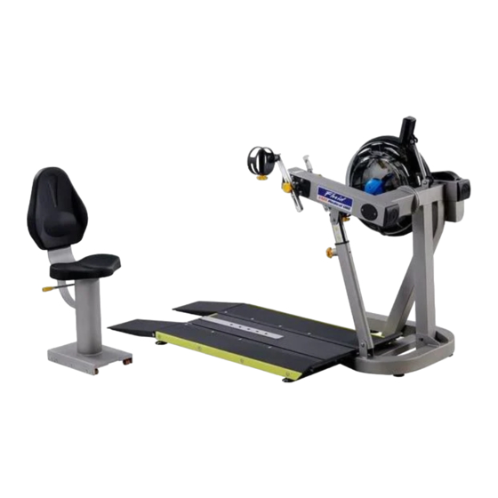
- Page 1 USER GUIDE E920A Wheelchair Accessible...
- Page 3 FIRST DEGREE FITNESS is proud to present the Rower as a FULL COMMERCIAL USE product featuring patented Adjustable Fluid Resistance. As with any piece of fitness equipment, consult a physician before beginning your E920A exercise program. Follow all instructions carefully for correct assembly, tank filling, water treatment, service and safety.
-
Page 4: Table Of Contents
Contents Safety ................... 5 Assembly ................7 E920A Box 1 & Box 2 Contents ..........8 Assembly Instructions ............. 9 Operation Instructions Bluetooth Auto-Adjust Monitor ..........19 Calibration Procedure ............20 Maintenance & Troubleshooting Tank Belt Adjustment International Warranty ............24... -
Page 5: Safety
Safety Safety Information • Before using this product, it is essential to read this ENTIRE operation manual and ALL instructions. The Rower is intended for use solely in the manner described in this manual. • UNDERSTANDING EACH AND EVERY WARNING TO THE FULLEST IS IMPORTANT •... - Page 6 Inspection • DO NOT use or permit use of any equipment that is damaged and/or has worn or broken parts. For all FIRST DEGREE FITNESS equipment use only replacement parts supplied by FIRST DEGREE FITNESS. • EQUIPMENT MAINTENANCE - Preventative maintenance is the key to smooth operating equipment as well as to keep your liability to a minimum.
-
Page 7: Assembly
Assembly Product Specifications Product Class: SC Braking System: Speed Independent Product Net Weight: 90kg (198lb) Product Gross Weight: 110kg (242lb) Maximum Safe Operating Surface Area: 301cm (108.27”) Length x 222cm (87.40”) Width Dimensions: 1810mm (71.26”) Length x 1020mm (40.16”) Width x 1480mm (58.27”) Height Maximum User Weight: 150kg (330lb) Footprint:2410mm x 1620mm... -
Page 8: E920A Box 1 & Box 2 Contents
E920A Box 1 & 2 Contents Item Qty. Description Item Qty. Description Main Frame with Telescoping Tube Plastic Spacer and Internal Gas Assist Shock Baseplate 3mm Allen Key Seat Frame Foot Levelers Seat Back Multi-tool Lower Seat D Cell Duracell Battery... -
Page 9: Assembly Instructions
Assembly Instructions STEP 1 Main Frame Assembly Instructions REQUIRED Attach Telescoping Tube to the underside of the 4 x M8 x 15mm Blots [19] control arm using 4x M8x15mm Bolts[19] and 4x M8 Spring Washers[29]. 4 x M8 Spring Washers [17] b) Thread the 3x Foot levelers[12] into underside of base. - Page 10 Assembly Instructions STEP 3a Installing Baseplate to the Main Frame REQUIRED T-Track Ramp Right T-Track Ramp Left 2 x PVC Side Covers 3 x M10x20mm Blots [23] 2 x M10 Nylock Nut [25] PVC Side Covers Ramp Right 3 x M10 Washer [28] Ramp Left Bolt the T-Track to the Main Frame as shown, using Remove contents from box...
- Page 11 Assembly Instructions STEP 3b Installing Baseplate to the Main Frame REQUIRED Attach Left and Right Ramps to the T-Track using 8x M8x45mm Bolts[22]. 4 x M8 x20mm Bolts [20] 4 x M8 x25 Blots [21] c) Once the Left and Right Ramps have been installed to the sides of the T-Track, secure the front end of each 8 x M8 x45mm Blots [22] Ramp as shown using 4x M8x25 Bolts[21], 4x M8...
- Page 12 Assembly Instructions STEP 4 Installing Seat Assembly Thread the Handle Bar[30] through the Shaft REQUIRED Seat Frame [3] Tighten the Handle Bar[30] with the M10 Dome Nut[30] . Seat Back [4] Install Seat Back[4] with 4x M6x20 Bolts[18] and M6 Lower Seat [5] Washer[26].
- Page 13 Assembly Instructions STEP 5 Installing Seat to the Main Frame Seat Stop: Must be lowered to allow seat onto CAUTION Baseplate track. Must ALWAYS be in the LOCKED position when seat is occupied on Baseplate. Must The Seat Stop Must be in the locked position whenever be lowered to allow seat removal.
-
Page 14: Operation Instructions
Operation Instructions E920 Control Arm Chain Tensioning Bolts: Allows for tightening the chain or adjustment from side to side. Make sure when tightening only to adjust the same amount for both Bolts, otherwise the sprocket will be misaligned. Note: Tightening the right Bolt only (turning clockwise) will pull the right side of the crank assembly toward you, tightening the left will pull the left side toward you. - Page 15 Operation Instructions Slider Arm Kit Installation Instructions Mount the left Slider Arm onto the Axle using the yellow indicator hole to align the slider and axle. Tighten the set screw onto the Axle and into the yellow indicator hole using the 3mm Allen key.
- Page 16 Operation Instructions Additional Exercises Training can now be achieved with both left and right Handgrips moving parallel , rather than in an opposed motion. a) On the right Slider Arm Assembly, remove the Adjustment Knob, loosen set screw and remove Assembly from the Axle.
- Page 17 (rechargeable via USB) available as an option. We recommend this to any commercial facility, with multiple units, that has a need to drain and refill Tanks from time to time. To purchase, contact your nearest First Degree Fitness distributor or go to our website on www.firstdegreefitness.com for details.
- Page 18 Operation Instructions CHANGING RESISTANCE LEVEL Changing resistance on your Unit is simple. The level of resistance is determined by the level indicator lo- cated on the front of the Tank. Level one indicates lightest resistance, level ten represents heaviest resistance. The Tank’s variable fluid resistance technology ensures an instant catch and constant resistance throughout the movement.
-
Page 19: Bluetooth Auto-Adjust Monitor
Bluetooth Auto-Adjust Monitor Auto Start: Commence exercise to activate. Reset all values: Press and hold RESET button for 3 seconds. Auto Power Down: Over 5 minutes. All values revert to zero after restart. WATT: Power measured in watts WORK: Duration of exercise segment REST: Duration of rest period POWER GRAPH: Press RESET to change display from Power Curve to Cumulative Power Graph... -
Page 20: Calibration Procedure
Calibration Procedure Press and hold 「RESET」and「REST」for 5 seconds. Display will show “ - - - - “ Turn handle to Level 1. Press Reset. Display will now show Level 2. Level 1 Calibration is complete. Turn handle to Level 2. Press Reset. -
Page 21: Maintenance & Troubleshooting
Tanks from time to time. To purchase, contact your nearest First Degree Fitness distributor or go to our website on www.firstdegreefitness.com for details. The computer display is erratic and It is possible that there is a loose connection. - Page 22 Crank Arm threads, necessitating securely tightened into replacement. Crank Arm. To ensure maximum lifespan and optimal performance follow these steps: Keep your E920A in a dry, clean climate controlled environment at room temperature. 2. Only treat water with FDF genuine Water Treatment Tablets.
-
Page 23: Tank Belt Adjustment
Tank Belt Adjustment 1. Remove large metal inspection plate. 2. Using a long tool, push out the rear end cap as pictured below left. This will give you access to the tank tensioning Bolt (shown lower right). End Cap 4. Using a 6mm Allen Key, tighten the 3. -
Page 24: International Warranty
Metal Frame – 10 Year Limited Warranty First Degree Fitness will repair or replace the metal Main Frame should it fail due to any defect in materials or workmanship within 10 years of the original purchase. Warranty does not apply to frame coating. - Page 28 CONTACT US For customer support please visit firstdegreefitness.com/support TAIWAN T: +886 3 478 3306 764 Chung Shan South Rd Yangmei Taoyuan Taiwan R.O.C.
Need help?
Do you have a question about the E920A and is the answer not in the manual?
Questions and answers